Page 6
CLEARANCES - Continued
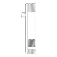
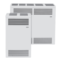
1. MINIMUM CLEARANCES
• Side Wall: Min. Clearance = 4”
(See Fig. 1) NOTE: The unit may be recessed and rest directly
against side studs and the inside surface of the rear wall.
• Ceiling: Min. Clearance = 4”
(See Fig. 1)
• Floor: Min. Clearance = 0”
(See Fig. 1)
•
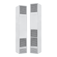
FromtheSideoftheVentCaptoAnyProtruding
ObstructionsorCorners: Min. Clearance = 12”
(See Fig. 2b)
•
FromanyWindowtotheSideoftheVentCap
DVCF553C, 554C, 557C and 558C
FIG. 2-B
12”
Min.
12”
Min.
24” Minimum
12” Minimum
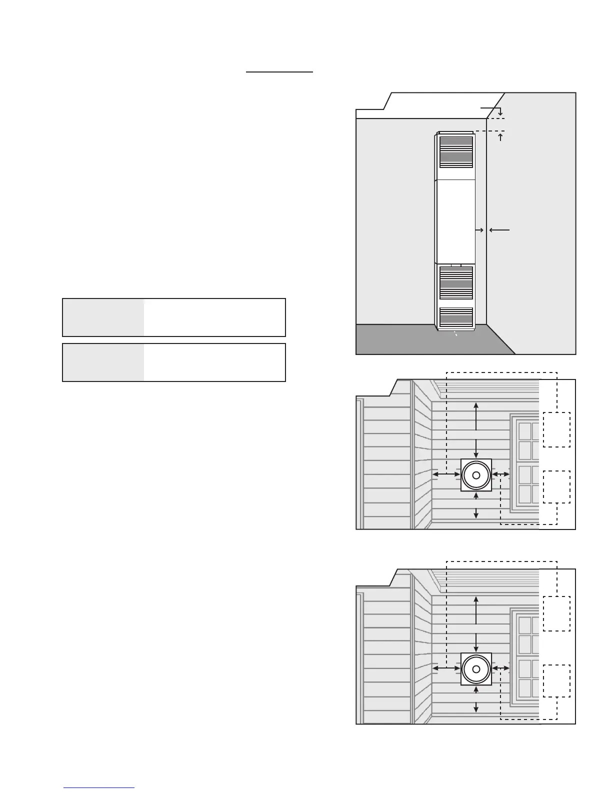
DVCF403C, 404C, 407C and 408C
FIG. 2-A
9”
Min.
12”
Min.
24” Minimum
12” Minimum
2. RESIDENTIAL GARAGE INSTALLATION:
Gas utilization equipment in residential garages shall be
installed so that all burners and burner ignition devices are
located not less than 18 inches (46 cm) above the oor. Such
equipment shall be located, or protected so it is not subject
to damage by a moving vehicle. Use care in selecting a good
location within the garage.
• DO NOT locate the appliance where heated air will
be directed onto a nearby parked vehicle.
• Paint may discolor or rubber
may harden and crack.
• DO NOT allow heated discharge air to blow directly
onto open or closed containers of paint, gasoline or
other liquids having ammable vapors.
DVCF403,404,
407,&408C
DVCF553,554,
557&558C
Min. Clearance = 9”
(See Figure 2)
Min. Clearance = 12”
(See Figure 2b)
•
FromanyOverhangingProjectiontoTopofVentCap
Min. Clearance = 24”
(See Figure 2)
CEILING
4” Minimum
4” Minimum
SIDE
WALL
FLOOR 0”
FIG. 1