©2017 Cradlepoint. All Rights Reserved. | +1.855.813.3385 | cradlepoint.com
3
Vehicle Installation Guide / IBR900/950/1100/1150
4/10/17
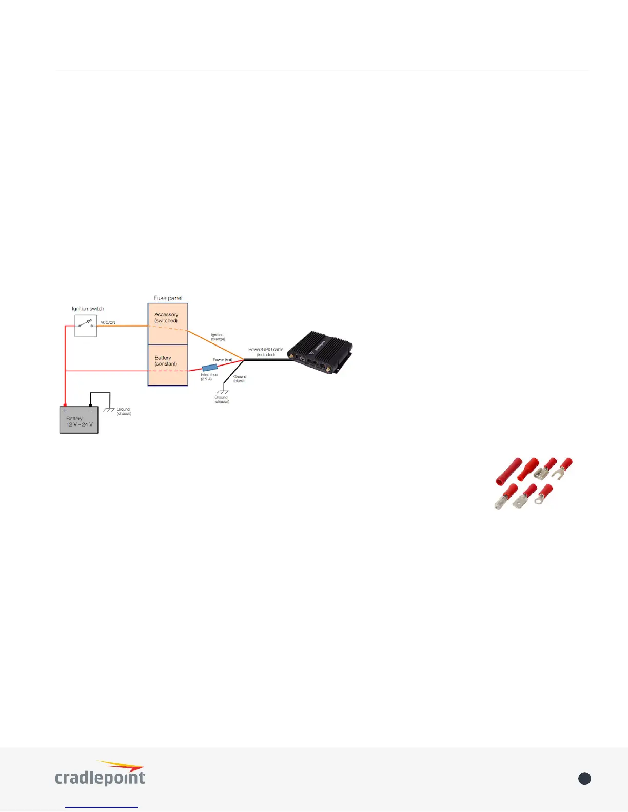
The wire colors shown are for the power/GPIO cable that is included with the COR IBR900/950 and IBR1100/1150
or available as an accessory. Other wiring setups may have dierent colors.
If you need a power/GPIO cable that is longer than two meters, we recommend the following wire gauges (AWG):
• 22 gauge wire for up to 4 meters (~13 ft)
• 20 gauge wire for up to 6 meters (~20 ft)
• 18 gauge wire for up to 12 meters (~40 ft)
For additional power source options, see the adapters and cables accessories page.
INSTALLATION
The red wire (power) should connect to the positive (red) terminal of the battery, and the black wire (ground)
should connect to the chassis. To enable ignition sensing functionality, connect the orange wire (input) to the
ignition, or accessory, switch. The power and ignition wires can be attached directly or through the fuse panel.
The red power wire requires an inline fuse at 2.0 or 2.5 A. Either use an extra slot in the fuse
panel for this fuse, or splice an inline fuse directly into the wiring. Here is an example of how
to attach an inline fuse: http://youtu.be/RDOZT-dTITo.
Wire connections vary depending on the installation. Make sure your connectors are rated for
the gauge of your wires (e.g., the included power/GPIO cable is 22 AWG). See the sample crimp
connectors at right, and see this video example for how to attach a quick splice connector:
http://youtu.be/zxt3LVpvjcw.
IGNITION SENSING
Ignition sensing allows you to set the router to power on when the ignition key is turned to ACC/ON, and then
power o after the ignition key is turned o with a designated time delay. For example, set your router to
remain on for an hour after the vehicle is turned o and then shut o. When the vehicle is turned on again, the
router will also turn back on.
Edit these settings on the GPIO Connector administration page. Go to the conguration pages for your device or
group in Enterprise Cloud Manager or log into the local device administration pages and go to SYSTEM > GPIO
Conguration. Refer to your product’s User Manual for GPIO conguration instructions.