10
Detailes:
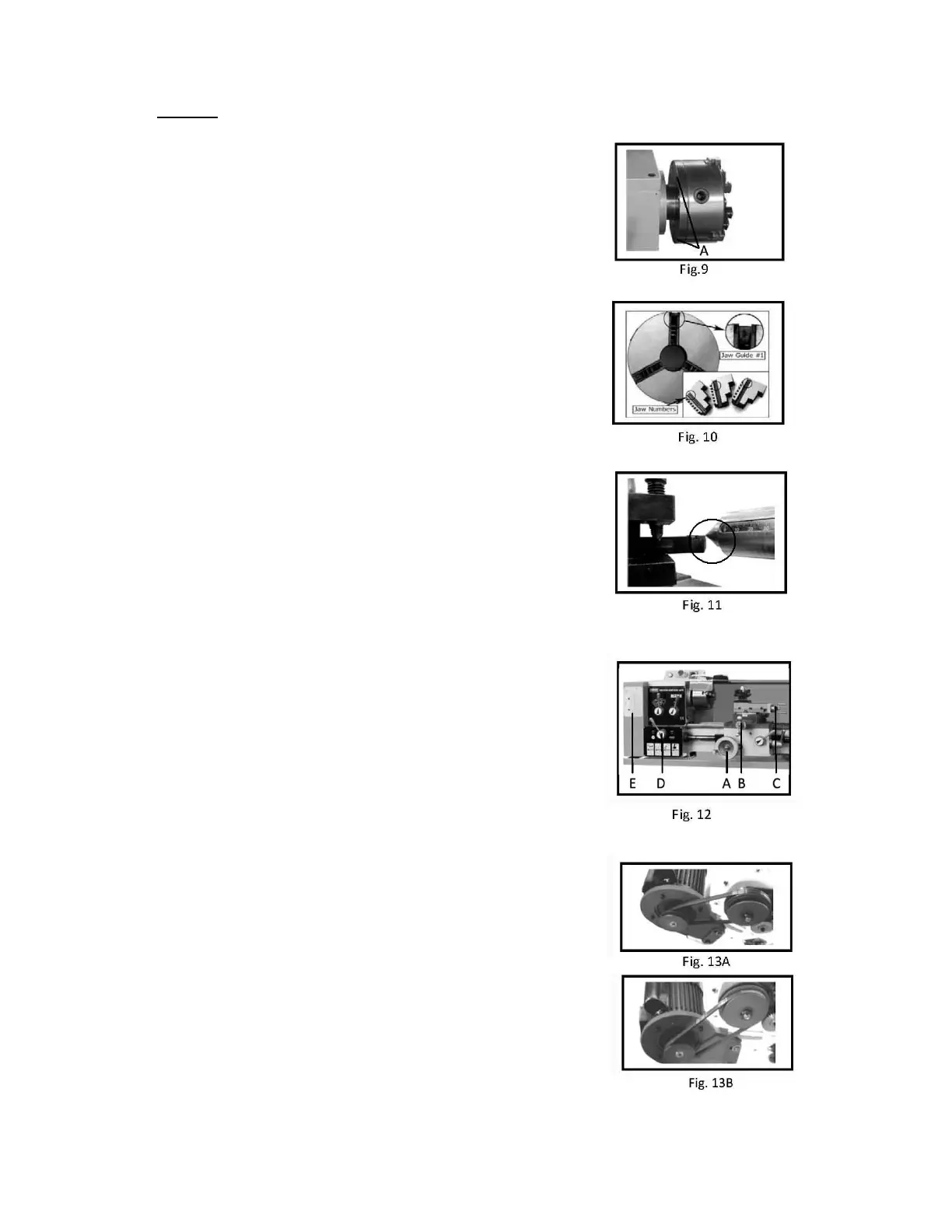
Replacement of Chuck
The head spindle holding fixture is cylindrical. Loose three set
Screw/nut(A. Fig. 9)on the flange to remove the chuck
Replace new chuck and fix it by the same set screws and nuts.
Replacement of Chuck Jaw Fig.9
5The jaws are in two types – the internal jaws and the external
Jaws(Fig. 10). Please pay notice that the number of jaws fit with
the number inside the chucks groove. Do not mix them together
When you are going to mount them, please mount them in
Ascending order, and when taking them out, take them out in
descending order (3-2-1) one by one. After finished this
procedure, rotate the jaws to the smallest diameter and make
sure there fit is right. Fig. 10
Tool Set-up
Set correction and clamp the cutting tool into the tool-post.
The tool must be clamped firmly. When turning, the tool has
a tendency to bend under the cutting force generated during
the chip formation(Fig. 11). For best results, tool overhang
should be kept to a minimum of 3/8” or less.
Fig. 11
Manual Turning
Handwheel of Apron travel(A), cross travel(B) and top slide(C)
can be operated for longitudinal or cross feeding (Fig. 12)
Longitudinal Turing with Auto-feeding
1. Set the selector knob (D. Fig. 12) to select the feed
Direction and the feed speed
2. Use the table (E. Fig. 12)on the lathe for selecting the feed
speed or the thread. Adjust the change gear if the required Fig. 12
feed or thread cannot be obtained with the installed gear set
Change High/low Speed
Set the belt in inside groove of pulley (Fig. 13A) is running
at high speed.
Likewise, remove the belt from inside groove (Fig. 13A) Fig. 13A
to outside groove (Fig. 13B) is to be run with low speed,
which should be removed by manual or tools.
 Loading...