Do you have a question about the Craftsman 113.23112 and is the answer not in the manual?
Read the owner's manual carefully to learn its applications, limitations, and potential hazards.
Ensure the tool is equipped with a proper grounding type plug and never connect the green wire to a live terminal.
Ensure all guards are in working order, proper adjustment, and alignment.
Develop the habit of checking to see that keys and wrenches are removed before turning the tool on.
Avoid cluttered areas; ensure the floor is not slippery due to wax or sawdust.
Do not use power tools in damp/wet locations or expose them to rain; keep work area well lighted.
Ensure all visitors are kept a safe distance from the work area.
Do not wear loose clothing; wear protective hair covering and roll up long sleeves.
Always wear safety goggles complying with ANSI Z87.1 during operation.
Use clamps or a vise to hold work when practical for safer operation.
Maintain proper footing and balance at all times.
Keep tools sharp and clean for best and safest performance.
Disconnect tools before servicing or changing accessories.
Ensure the switch is in the "OFF" position before plugging in.
Consult the owner's manual for recommended accessories.
Avoid standing on the tool to prevent injury if tipped or contacting the cutting tool.
Carefully check any damaged guards or parts to ensure proper operation.
Feed work into a blade or cutter against the direction of rotation.
Turn power off and ensure the tool comes to a complete stop before leaving.
Ensure assembly, alignment, and operating familiarity are completed before connecting power.
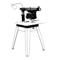
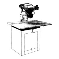
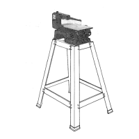
Properly set carriage lock, bolt saw to floor, and mount at correct height.
Avoid awkward positions, reaching around tools, and ensure proper guards are used.
Understand kickback causes and use push sticks, proper alignment, and guards.
Always return carriage to rear, keep guards horizontal, and never gang crosscut.
Use only recommended accessories and follow specific safety instructions.
Always wear safety goggles before commencing power tool operation.
List of tools required for assembly and setup.
Procedure to ensure the framing square is true for accurate alignments.
Familiarize yourself with the locations and functions of all saw controls.
Steps for unpacking components and initial preassembly before power connection.
Instructions for mounting the saw to a base, leg set, or flat bench.
Attaching the elevation crank and managing carriage stop components.
Step-by-step instructions for safely removing the saw blade.
Attaching and leveling table mounting support channels.
Checking for and removing looseness in the column tube support.
Squaring the cross cut travel for accurate linear movement.
Procedure to ensure the front table surface is perfectly level.
Positioning and installing the remaining rear table boards and clamps.
Adjusting the saw blade to be square with the work table.
Aligning the saw blade to the rip fence to correct 'heel' or 'toe'.
Properly positioning and adjusting the anti-kickback and spreader assembly for ripping.
Installing and adjusting the rip scale indicator for quick settings.
Familiarize yourself with the six diagrams and controls on the radial arm.
Using the elevation crank to raise or lower the saw blade.
Releasing, securing, and indexing the radial arm's miter angle.
Operating the swivel latch-pin knob and yoke clamp handle.
Securing the carriage on the radial arm for stable operation.
Using bevel lock and index knobs to set the blade's tilt angle.
Utilizing the locking feature to prevent unauthorized use.
Using the brake button to reduce blade coasting time after power off.
Properly positioning the guard and anti-kickback assembly for ripping.
A technique for accurate settings by indexing in one direction.
Setup requirements before performing crosscut operations.
Process of sawing workpiece by pulling the blade through it.
Using a clamp to limit carriage travel for multiple cuts.
Sawing a board at an angle other than 90 degrees.
Sawing with the blade set at an angle to the saw table.
Combining miter and bevel crosscuts for complex cuts.
Setup requirements before performing ripping operations.
Feeding workpiece into the blade using the fence as a guide.
Performing in-ripping or out-ripping with the saw blade tilted.
Guidelines for operating the dado head, including width and depth limits.
Instructions for operating the molding head or drum sander.
Details motor specifications, voltage, amperage, and RPM.
Saw wired for 120V, requires 15-AMP branch circuit and fuse/breaker.
Warning about potential electrical shock hazard if not properly grounded.
Ensuring use of a 3-conductor grounded type outlet or adapter.
Recommendations for motor maintenance, cleaning, and protection.
Troubleshooting steps for motor failure to start or sudden stalling.
Guidance on selecting appropriate wire gauge for extension cords.
Addressing looseness in the column tube support affecting elevation crank.
Troubleshooting inaccurate 0° or 45° miter crosscut angles.
Resolving issues with cuts not being 90° to the table top.
Correcting inaccuracies in blade angle (bevel) cuts.
Addressing rough kerf edges, commonly called 'heel' or 'toe'.
Troubleshooting wood binding, smoking, or motor slowdown during ripping.
Diagnosing and fixing boards that pull away from the fence during ripping.
Testing for and adjusting looseness in carriage bearings.
Resolving problems with the yoke not indexing properly.
Adjusting the yoke clamp handle for proper locking position.
Diagnosing and resolving issues when the motor fails to start.
Troubleshooting low power output or motor slowdown.
Identifying causes and remedies for motor overheating.
Addressing slow motor startup or stalling during operation.
Resolving issues with fuses blowing or circuit breakers tripping.
Turn switch OFF and remove plug before any maintenance or lubrication.
Understanding which points require lubrication and which do not.
Carriage ball bearings, motor bearings, and between arm cap/arm do not need lube.
Lubricating swivel latch pin, column tube, keyway, and elevation crank shaft.
Excessive oil attracts airborne dust and sawdust.
List of available accessories with their corresponding catalog numbers.
Read and comply with safety instructions before using accessories.
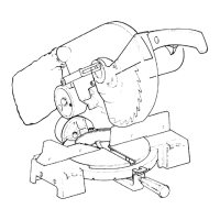
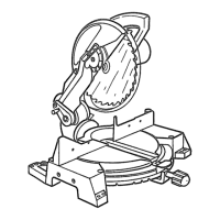
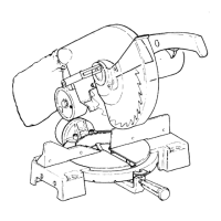
Diagram and list of parts for the radial saw.
Diagram and list of parts for the radial saw.
Diagram and list of parts for the radial saw.
Diagram and parts list for the motor assembly.
Diagram and parts list for the guard assembly.
How to contact Sears Service Center for repairs or service.
Locating the model number on the saw's rear left-hand side plate.
Required information when ordering repair parts (Part Number, Description).
| Model Number | 113.23112 |
|---|---|
| Type | Table Saw |
| Blade Diameter | 10 inches |
| No Load Speed | 3450 RPM |
| Max Cut Depth at 90° | 3-1/8 inches |