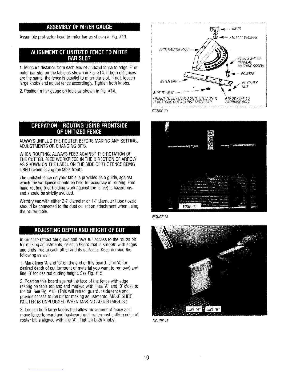
Assembleprotractor headtOmiter baras shown in Fig.#13.
1.Measuredistancefrom each endof unitizedfenceto edge'E' of
miter barslot on thetable as shownin Fig.#t4. If both distances
arethe same,the fenceis parallelto miter barsfot. !t not, loosen
largeknobs andadjust fenceaccordingly,Tightenboth knobs.
2.Position miter gaugeon tableas shown in Fig #14.
.._4-417X 3/4 LG
,_" PANHEAD
MACHINESCREW
__"t¢"*......._ -_-- POtNTER
HEX
/
3,'t6'f'ALNUT............... \,
PALNU_TOBE PU,S'HEOONTOSTUDUNTIL #t0-32 x 3,;4"LG.
tT BOTTOMSOUTAGAINSTMtTER BAR CARRtAGEBOLT
FIGURE13
ALWAYSUNPLUGTHEROUTERBEFOREMAKINGANY SETTING,
ADJUSTMENTSORCHANGINGBITS,
WHENROUTING,ALWAYSFEEDAGAINSTTHEROTATIONOF
THECUFrER FEEDWORKPIECEIN THEDIRECTIONOFARROW
AS SHOWNONTHELABELONTHESIDEOFTHEFENCEBEING
USED(when facingthe tablefront).
Theunitizedfenceon your table is providedasa guide, against
whichthe workpieceshould be heldfor accuracyin routing. Free
handrouting (notholding work againstthe fence)is hazardous
andshouldbestrictly avoided.
Wet/dryvacwith eitller 2S" diameteror 1/" diameterhose nozzle
shouldbe connectedto the dust collectionattachmentwhen using
theroutertable,
FIGUREt4
tn orderto retractthe guardand haveful! accessto the routerbit
for makingadjustments,selecta boardthat is smooth with edges
and endstrue to eachotherand its surfaces,Keepin mind the
foi!owingaswel!:
1.Mark lines'A and 'B'on the endof this board. Line'A' for
desireddepth of cut (amount of materialyouwant Io remove)and
line'B' for desiredcutting heighLSeeFig.#I 5,
2. Positionthis boardagainsttheface of tile fencewith edge
restingon tabletop and endmarkedwith lines 'A' and 'B' dose to
the bit. SeeFig,#t5. (Thiswill retractguard inside tenceand
provideaccessto the bit for makingadjustments,MAKESURE
ROUTERtSUNPLUGGEDWHENMAKINGADJUSTMENTS.)
3,Loosenbothlargeknobs thatallow movementoffence and
movefenceforwardand backwarduntil outermostcutting edgeef
routerbit is alignedwith line 'A'. Tightenboth knobs. FfGUREt5
t0
 Loading...