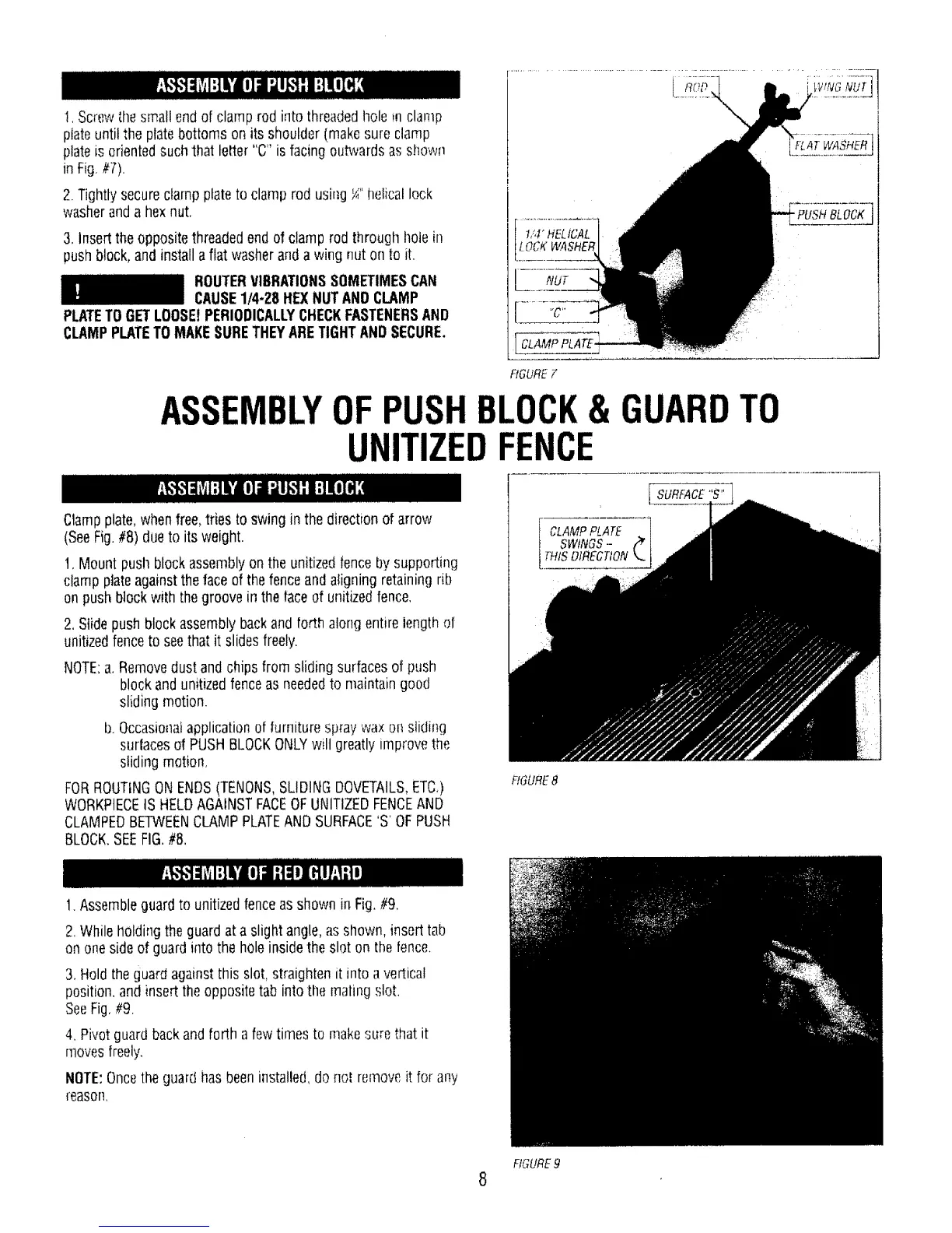
!, Screwthesmall endof clamp rod into threadedhole m clamp
ptateuntilthe platebottoms on its shoulder (makesureclamp
plateisorientedsuch that letter "C" is facing outwardsas shown
in Fig,//7).
2. Tightlysecureclamp plateto clamp rod using_" helicallock
washerand a hexnut.
3, Inserttheoppositethreadedendof clamp rod through hole in
pushblock, and installa flat washeranda wing nut on to it.
ROUTERVIBRATIONSSOMETIMESCAN
CAUSE1/4-28 HEXNUTANOCLAMP
PLATETOGETLOOSEtPERIODICALLYCHECKFASTENERSAND
CLAMPPLATETOMAKESURETHEYARETIGHTANDSECURE.
, NUT
i[ CLAMPPLATE-
RGURE F
i
'FLAT WASHER
" PUSH BLOCK
ASSEMBLYOF BLOCK& GUARDTO
UNITIZED
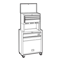
Clampplate,whenfree,tries to swing in the directionof arrow
(SeeFig.#8) due to its weight.
t. Mount pushblockassemblyon the unitizedfenceby supporting
clampplateagainsttheface ofthefenceand aligning retaining rib
on pushblockwith thegroove in the faceof unitizedfence,
2.Slide pushblockassemblybackand forth alongentirelengthof
unitizedfenceto seethat it slidesfreely.
NOTE:a, Removedustand chips from sliding surfacesof push
blockand unitizedfenceas neededto maintaingood
slidingmotion.
b,Occasionalapplicationof furniturespray wax on sliding
surfacesof PUSHBLOCKONLYwilt greatly in]provethe
sliding motion,
FORROUTINGON ENDS(TENONS,SLIDINGDOVETAILS,ETC,)
WORKPIECEIS HELDAGAINSTFACEOFUNITIZEDFENCEAND
CLAMPEDBETWEENCLAMPPLATEANDSURFACE'S'OFPUSH
BLOCK.SEEFIG.#8.
FIGURE8
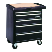
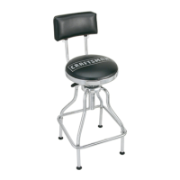
1.Assembleguardto unitizedfenceasshown in Fig,#9,
2.Whileholdingthe guardat a slight angle,asshown, inserttab
on onesideof guardinto the holeinsidetheslot on the fence.
3,Holdtheguard againstthis slot, straighten it into avertical
position,and insert the oppositetab intothe matingslot.
SeeFig,#9.
4, Pivotguardbackand forth a fewtimes to makesure that it
movesfreely.
NOTE:Oncethe guard has beeninstalled,do nol removeit for any
reason,
FIGURE9
8