8
ASSEMBLY
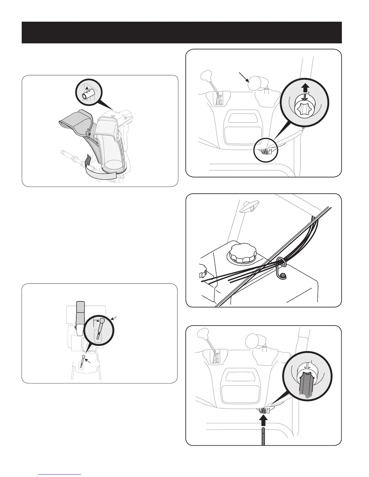
4. Squeeze the trigger on the joystick, rotate the chute assembly by
hand to face forward. The holes in the chute rotation assembly
should be facing up. See Figure 5.
NOTE: The chute will not rotate without squeezing the trigger on the
joystick.
5. Rotate the joystick to 1 o’clock position (see Figure 6) so the silver
arrow on the pinion gear faces upward (see Figure 7).
NOTE: The pinion gear is located on the front of the unit below the
control panel.
NOTE: The joystick must be angled slightly to the right as shown
Figure 6 and the arrow on the pinion gear at the top to ensure full chute
rotation.
6. It is important that all cables be routed through the cable guide
and remain positioned on the left side of the chute control rod. See
Figure 8.
7. While supporting the back of the pinion gear insert the hex end of
the chute control rod (hole pointing upward) into the pinion gear.
See Figure 9.
Figure 5
Figure 7
Top
JoystickJoystick
Joystick in the
1 o’clock position.
Figure 6
Figure 8
Figure 9