Unigen Plus & Industrial Unigen - User technical documentation
-D page 14/19
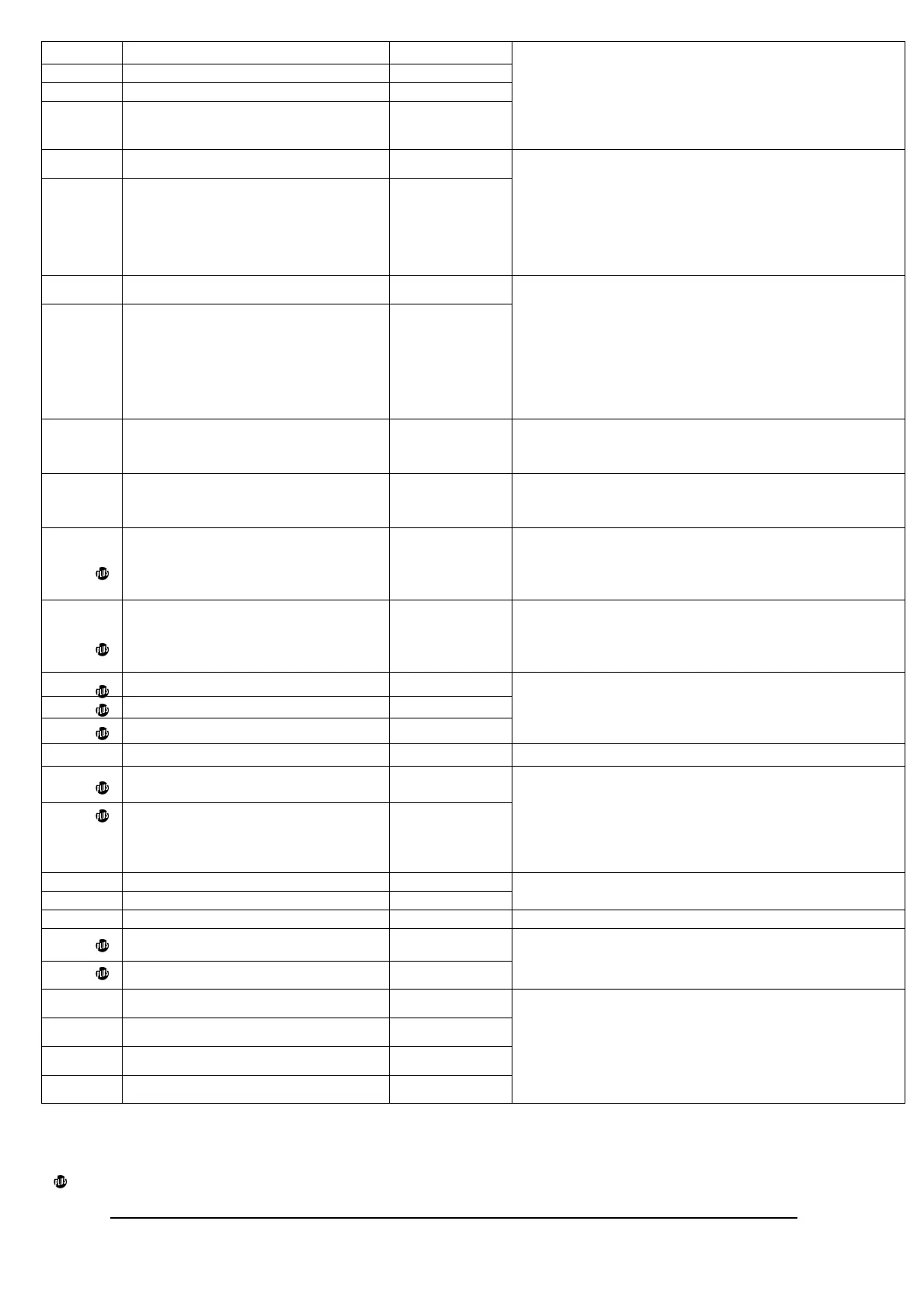
28
Generator L1 1.5 / 16
29
Generator L2 1.5 / 16
30
Generator L3 1.5 / 16
31
Generator Neutral 1.5 / 16
AC voltage input measurement generator.
Line to line voltage from 100 to 500 VAC.
Frequency: 50 or 60 Hz.
Fuses: 100 mA. / 600 VAC.
Note: If the neutral input is not connected, UNIGEN will
generate an internal virtual neutral point.
32
START ON LOAD REQUEST 1 / 17
33
START ON LOAD REQUEST 1.5 / 16
Dry contact: Normally open, 250 VAC, 5A.
‘START ON LOAD REQUEST’ relay is closed when the
load request exceeds 80% of the nominal power ->
slave generator is to start.
‘START ON LOAD REQUEST’ relay is opened when
the load request is above 20% of the nominal -> Slave
generator is to stop.
34
SYNC OK 1.5 / 16
35
SYNC OK 1.5 / 16
Dry contact: normally open, 250 VAC, 5A.
‘SYNC OK’ relay is closed when the coupling of the
generators is safe
(‘sw5’ and ‘sw6’ configuration)
:
- Voltage difference within limits.
- Phase difference within limits.
- Frequency difference within limits.
- Phase sequence
- or Deadbus
36
SET UNAVAILABLE 1 / 17
Not isolated digital input, Dry contact to 0v
(10 kOhms pull-up).
Connect the signal "fault" from the generator.
37
SLAVE INPUT 1 / 17
Not isolated digital input, Dry contact to 0v
(10 kOhms pull-up).
Select this UNIGEN in slave.
38
MAINS PARALLELED (for Unigen
Plus)
1 / 17
Not isolated digital input, Dry contact to 0v
(10 kOhms pull-up).
This input gives the position of mains breaker to the
UNIGEN. Use a direct Aux contact of the breaker.
39
COMMAND MODE (for Unigen Plus)
1 / 17
Not isolated digital input, Dry contact to 0v
(10 kOhms pull-up).
This input forces kW and kVAR load sharing in
COMMAND MODE.
40
KW SET CW +5V (for Unigen Plus) 0.25 / 23 *
41
KW SET cursor (for Unigen Plus) 0.25 / 23 *
42
KW SET CCW 0V (for Unigen Plus) 0.25 / 23 *
Analog input 5 kOhms potentiometer or 0-5 VDC
between 42 (-) and 41 (+). Use a shielded wire.
43
Not connected
44
Parallel lines High(+)(for Unigen
Plus)
2.5 / 13*
45
Parallel lines low(-)(for Unigen Plus) 2.5 / 13*
0 to 3V. Isolated input.
Load sharing and power set level (kW only)
(‘sw3’ to
OFF configuration).
Compatibility with other UNIGEN and with analogue
load sharing line isolated or not isolated (ex: GCR).
Compatibility with Wheaston bridge.
46
CANBUS+ 2.5 / 13*
47
CANBUS- 2.5 / 13*
Isolated input. Load sharing with canbus
(‘sw3’ to ON
configuration for Unigen Plus) (‘sw1’ configuration).
48
SHIELD 0.25 / 23 * Terminal to connect the shield of the CAN signals.
49
MODBUS A (for Unigen Plus) 2.5 / 13 *
50
MODBUS B (for Unigen Plus) 2.5 / 13 *
19200 bps. Used to communicate with SCADA.
MODBUS RTU slave. Read (04 and 03) functions.
(‘sw8’ configuration).
51
Bus bar L1 1.5 / 16
52
Bus bar L2 1.5 / 16
53
Bus bar L3 1.5 / 16
54
Bus bar Neutral 1.5 / 16
AC voltage input measurement bus bar.
Line to line voltage from 100 to 500 VAC.
Frequency: 50 or 60 Hz.
Fuses: 100 mA. / 600 VAC.
Note: If the neutral input is not connected, UNIGEN will
generate an internal virtual neutral point.
Note: * Shielded cable is recommended for these connections. Use 2 or 3 Conductor Foil Shield with drain Wire.
Note: Cable sizes are for guidance only. Cable size should be increased for long cable runs, to overcome possible
voltage drop and to increase noise immunity.
Only for Unigen Plus.
 Loading...
