Unigen Plus & Industrial Unigen - User technical documentation
-D page 5/19
2. Features
2.1. Synch check relay
SYNC OK output (terminal 34/35) permit the coupling of generators when all following conditions are correct:
• Voltage of generator and bus bar within a 15 - 130% window from nominal voltage (500V).
• Voltage difference between generator and bus bar, < 10%
• Frequency of generator and bus bar within a 30 - 130% window from nominal frequency
• Phase Angle difference between generator and bus bar. <+/- 10°
• Frequency difference between generator and bus bar, < 0,01Hz
• Phase sequence correct.
The ‘SYNC OK’ output is depending of ‘SYNC IN’ (terminal 3), ‘sw5’, ‘sw6’, correct conditions and deadbus.
‘sw5’ is to authorize or not the coupling when the ‘SYNC IN’ is not connected.
‘sw6' is to authorize or not the coupling when the generator is on deadbus bar.
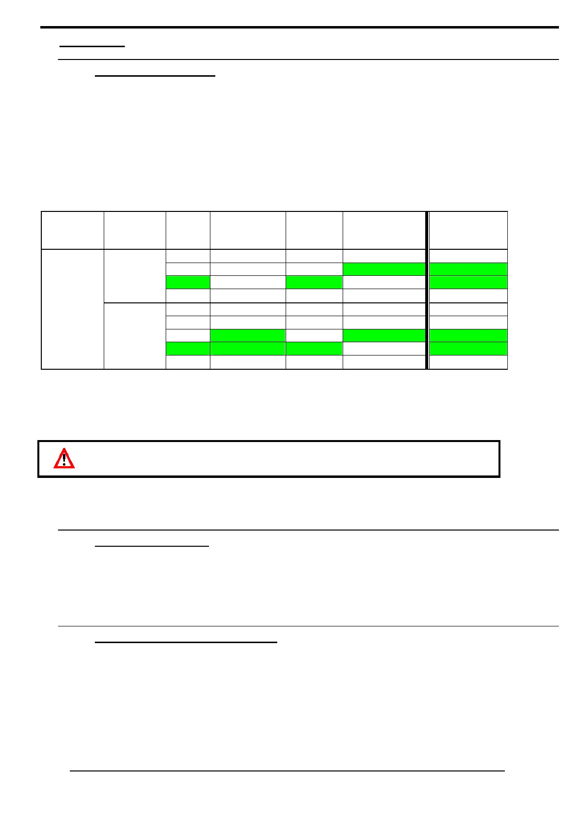
Behaviour of ‘SYNC OK’ is described in the following table:
Terminal 5
‘Breaker in’
Terminal 3
‘sync in’
sw6
deadbus
sw5
synchronization
Deadbus
(no voltage
on the bus)
∆φ∆Hz∆V phase
sequence
Terminals 34/35
‘sync ok’
OFF X X nok open
X X no ok close
ON X yes nok close
close
ON X no nok open
X OFF X X open
OFF ON X nok open
X ON no ok close
ON ON yes nok close
open
open
ON ON no nok open
Close: connected to the 0VDC.
Open: not connected.
X: no matter.
The relay is closed when the conditions are correct.
At start, on deadbus, there is a delay before closing the ‘SYNC OK’ relay (E01033, default value 3.0s).
The ‘SYNC OK’ green LED confirms the activation of the relay:
• LED ON = contact closed
• LED OFF = contact open
2.2. Reverse kW relay
UNIGEN includes a reverse Kw relays, terminal 9 & 10.
This relay output closes when the Kw of the generator is below -5% of the nominal Kw during more than 20 seconds.
The ‘REV. kW’ red LED confirms the activation of the relay:
• LED ON = contact closed
• LED OFF = contact open
2.3. Remote speed control input
• UNIGEN includes a remote speed control input on terminals 14, 15 and 16.
Those 3 wires inputs (+5v, cursor, -5v) are design to accept 5 kOhms external potentiometers.
The mid point of those potentiometers (5 turns for a 10 turns potentiometer) will generate a 0V signal to the cursor
input and will not generate any speed deviation.
The maximum speed deviation is + / - 3,00Hz:
• +5V applied on cursor input will increase the speed of + 3,00Hz
• -5Vapplied on cursor input will decrease the speed of -3,00Hz
This input can also be used as 0-5Vdc for a master PLC control. In this case the nominal speed have to be adjusted
with 2.5 VDC applied on cursor input.
One generator has to be started alone to close on the dead bus before starting the other
generators.