Unigen Plus & Industrial Unigen - User technical documentation
-D page 15/19
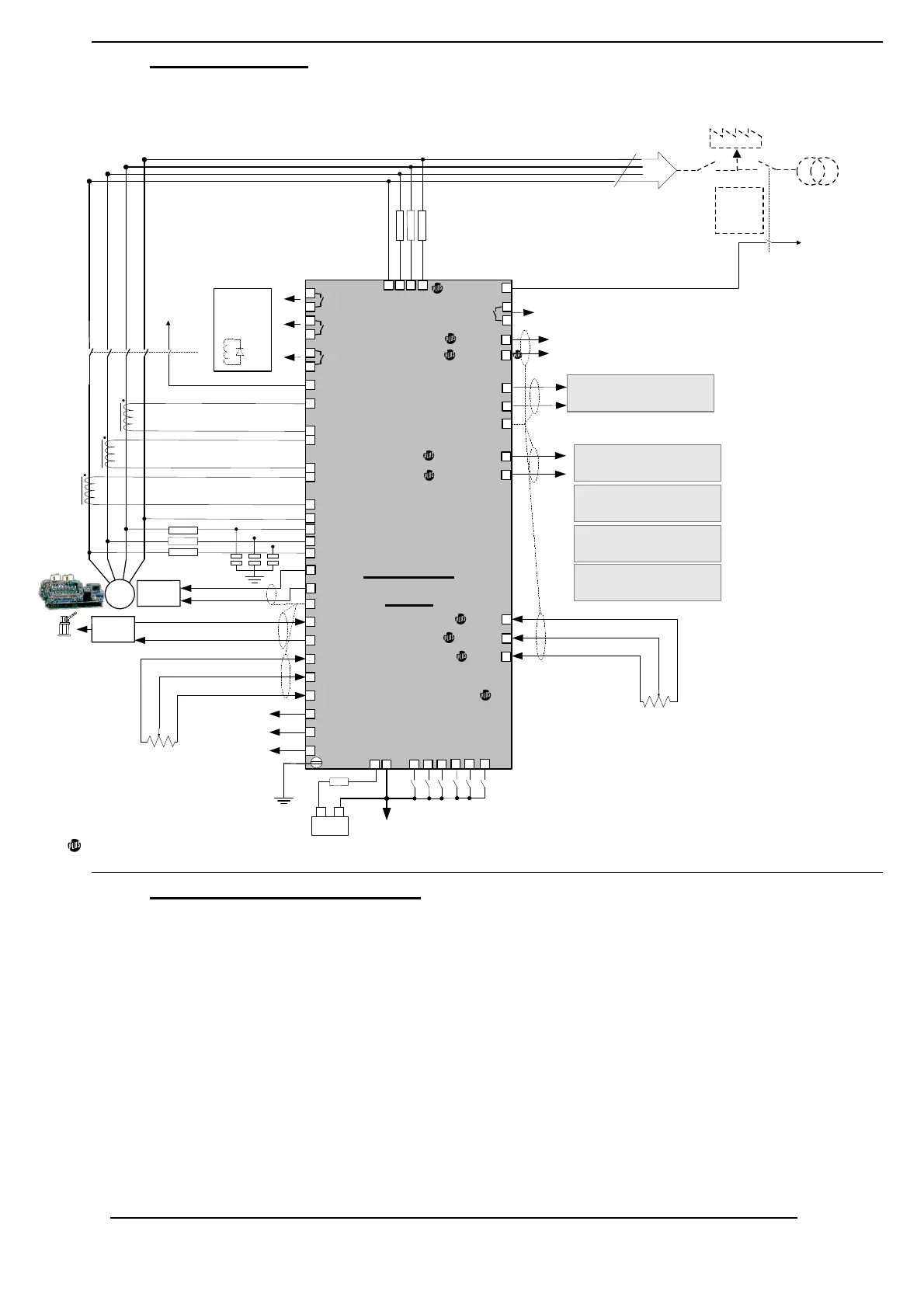
5.2. Wiring diagram
Each terminals of the industrial Unigen are on the Unigen Plus.
UNIGEN
plus
S
p
e
e
d
g
o
v
e
r
n
o
r
-
A
l
i
m
17
Speed out
23
Gen I1-
24
Gen I2+
25
Gen I2-
26
Gen I3+
27
Gen I3-
S
y
n
c
h
O
K
N
O
16
Speed CCW -5V
15
Speed CW +5V
14
1
P
o
w
e
r
s
u
p
p
l
y
+
2
p
o
w
e
r
s
u
p
p
l
y
-
18
Speed Ref
28
Gen L1
29
Gen L2
30
Gen L3
31
Gen N (optional)
22
Gen I1+
C
h
a
s
s
i
s
i
s
o
l
a
t
e
d
f
r
o
m
p
o
w
e
r
s
u
p
p
l
y
F
r
o
m
s
p
e
e
d
g
o
v
e
r
n
o
r
s
4
m
m
²
w
i
r
e
19
3
breaker IN
4
5
U
n
l
o
a
d
S
y
n
c
i
n
Trip out
NO
11
12
kW out +5V
kW out 0
Power monitor
0-5V or 0-20mA
6
D
r
o
o
p
Speed setpoint
Rev. kW
NO
13
kW out 20mA
-
B
a
t
t
e
r
y
+
5
A
m
p
s
L
o
a
d
Auto
Mains
Failure
L
2
N
L
3
L
1
+
/
-
5
V
o
r
p
o
t
e
n
t
i
o
m
e
t
e
r
5
k
O
h
m
s
analog
F
100 - 480 V
S
u
r
g
e
d
i
v
e
r
t
e
r
P
1
P
2
S
1
S
2
P
1
P
2
S
1
S
2
P
1
P
2
S
1
S
2
5 A
-
A
l
i
m
Breaker
control
34
35
9
10
8
7
G
F
F
F
+
A
l
i
m
L
2
N
L
3
L
1
100 - 480 V
51
Bus L1
52
Bus L2
53
Bus L3
54
(optional) Bus N
F
F
F
47
CAN-
CAN+
46
48
CRE
UNIGEN
A
V
R
20
AVR out +
21
AVR out -
S
t
a
r
t
o
n
l
o
a
d
r
e
q
u
e
s
t
N
O
32
33
36
S
l
a
v
e
i
n
p
u
t
37
S
e
t
u
n
a
v
a
i
l
a
b
l
e
45
44
CRE
UNIGEN
Barber Colman
PowRcon
Barber Colman
DYN2-80109
Woodward
2301A
...
Parallel lines high
Parallel lines low
41
40
42
C
o
m
m
a
n
d
m
o
d
e
38
CCW 0V
CW +5V
KW setpoint
+
/
-
5
V
o
r
p
o
t
e
n
t
i
o
m
e
t
e
r
5
k
O
h
m
s
39
M
a
i
n
s
p
a
r
a
l
l
e
l
e
d
49
50
Modbus A
Modbus B
R
S
4
8
5
-
A
l
i
m
Only for Unigen Plus.
5.3. Connection specifications
• Power supply: 9 to 40 VDC, <1A with 12 VDC and <500mA with 24 VDC.
• AC voltage inputs: 100 to 500 VAC, 100mA max. The neutral wire can be connected or not.
• AC currents inputs: 0 to 5A, 1VA. Each input is isolated from the other ones.
• Possible over-current: 15A during 10s.
• Frequency measurement: 45 to 70 Hz – 15 VAC minimum between neutral and line.
• Digital inputs: Normally Open, to be connected to 0v (internal pull up of 10 kOhms).
• Relay outputs: 5A, 230 VAC max.
• Remote speed control input: potentiometer (5 kOhms) or -5 +5VDC.
• Remote kW control input for ‘Command mode’: potentiometer (5 kOhms) or 0 +5VDC.
• Kw monitor output (0-5 V or 0-20ma/4-20mA): the maximum load impedance for the 0-20 mA. Or 4-
20mA. is 300 Ohms and the minimum load impedance for the 0-5 VDC is 1 K/Ohms.
• Speed bias output: The frequency control is made by the adjustable 0-10 VDC output. The
adjustments are, Offset and Gain potentiometers.
• Voltage bias output: The voltage control is done via the AVR. The output is a +/-10V, output with Gain
and Offset adjustments.
• Terminals: with screws, 2.5 mm
2
.