Unigen Plus & Industrial Unigen - User technical documentation
-D page 13/19
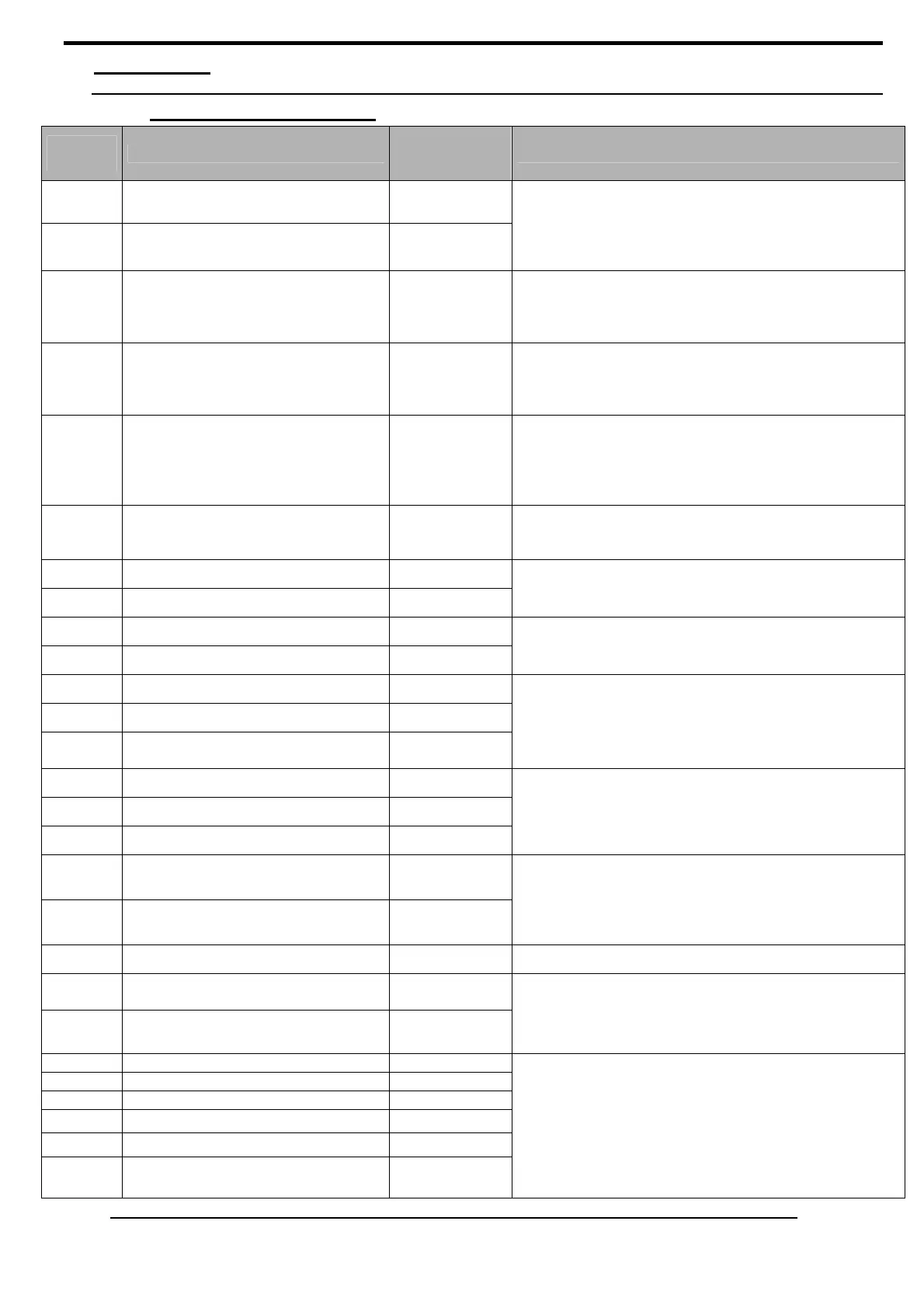
5. Terminals
5.1. Terminals description
Terminal
n°
Description
Wire
Recommended
mm² /AWG
Commentaries
1
POWER SUPPLY + 2.5 / 13
2
POWER SUPPLY - 2.5 / 13
DC Voltage from 9 to 40 VDC, 10 Watt.
Twist protection.
Note: Terminal 2 must be connected to both 0v of the
speed governors with a 4 mm² wire.
Fuse: 5 Amps / 40 VDC.
3
SYNC IN 1 / 17
Not isolated digital input, Dry contact to 0v
(10 kOhms pull-up).
This input activates the automatic synchronization
(‘sw5’ and ‘sw6’ configuration)
.
4
DROOP 1 / 17
Not isolated digital input, Dry contact to 0v
(10 kOhms pull-up).
This input forces kW and kVAR load sharing in DROOP
mode.
5
BREAKER IN 1 / 17
Not isolated digital input, Dry contact to 0v
(10 kOhms pull-up).
This input gives the position of generator breaker to the
UNIGEN.
Use a direct Aux contact of the breaker.
6
UNLOAD 1 / 17
Not isolated digital input, Dry contact to 0v
(10 kOhms pull-up).
This input generate an unload ramp generator.
7
TRIP OUT 1 / 17
8
TRIP OUT 1 / 17
Dry contact: normally open. 250 VAC, 5A.
This output controls the opening of generator breaker
at the end of the unload ramp.
9
REV KW 1 / 17
10
REV KW 1 / 17
Dry contact: normally open. 250 VAC, 5A.
The relay is closed when generator is in reverse power.
11
KW monitor (0 – 5V) + 1.5 / 16
12
KW monitor (0V) 0.25 / 23
13
KW monitor (0 - 20mA) +
or (4 - 20mA) +
0.25 / 23
DC analogue output. 0 – 5V (Terminals 11 and 12),
0 – 20mAmps or 4-20mAmps (Terminals 12 and 13)
(‘sw4’
configuration).
This output (voltage and/or current) sends the actual
value of kW generator.
14
SPEED SET CW +5V 0.25 / 23 *
15
SPEED SET cursor 0.25 / 23 *
16
SPEED SET CCW -5V 0.25 / 23 *
Analogue input 5 kOhms potentiometer or -5/+5 VDC
between 2(-) and 15(+). Use a shielded wire.
This input allows a manual remote control of generator
speed.
17
Generator OUT speed control output 0.25 / 23 *
18
Generator REF from speed governor
speed control output
0.25 / 23 *
Analogue output +/-10 VDC. Use a shielded wire.
This output controls the speed of generator. Offset and
gain potentiometers, this output is compatible with all
speed governors of the market.
(
‘sw2‘configuration)
19
Shield 0.25 / 23 * Terminal to connect the shield of the analogue signals.
20
AVR OUT (+) 0.25 / 23 *
21
AVR OUT (-) 0.5 / 20 *
Isolated analogue output +/-10 VDC.
This output controls alternator voltage. Offset and gain
potentiometers, this output is compatible with all AVRs
of the market.
22
Generator I1+ 2.5 / 13
23
Generator I1- 2.5 / 13
24
Generator I2 + 2.5 / 13
25
Generator I2 - 2.5 / 13
26
Generator I3 + 2.5 / 13
27
Generator I3 - 2.5 / 13
AC current inputs from generator.
Current: from 0 to 5 A. Max current: 15 A during 10s.
Load: 1 VA.
The nominal current of the secondary of the current
transformers must be as close as possible to 5Amps.
 Loading...
