Unigen Plus & Industrial Unigen - User technical documentation
-D page 12/19
4. Display
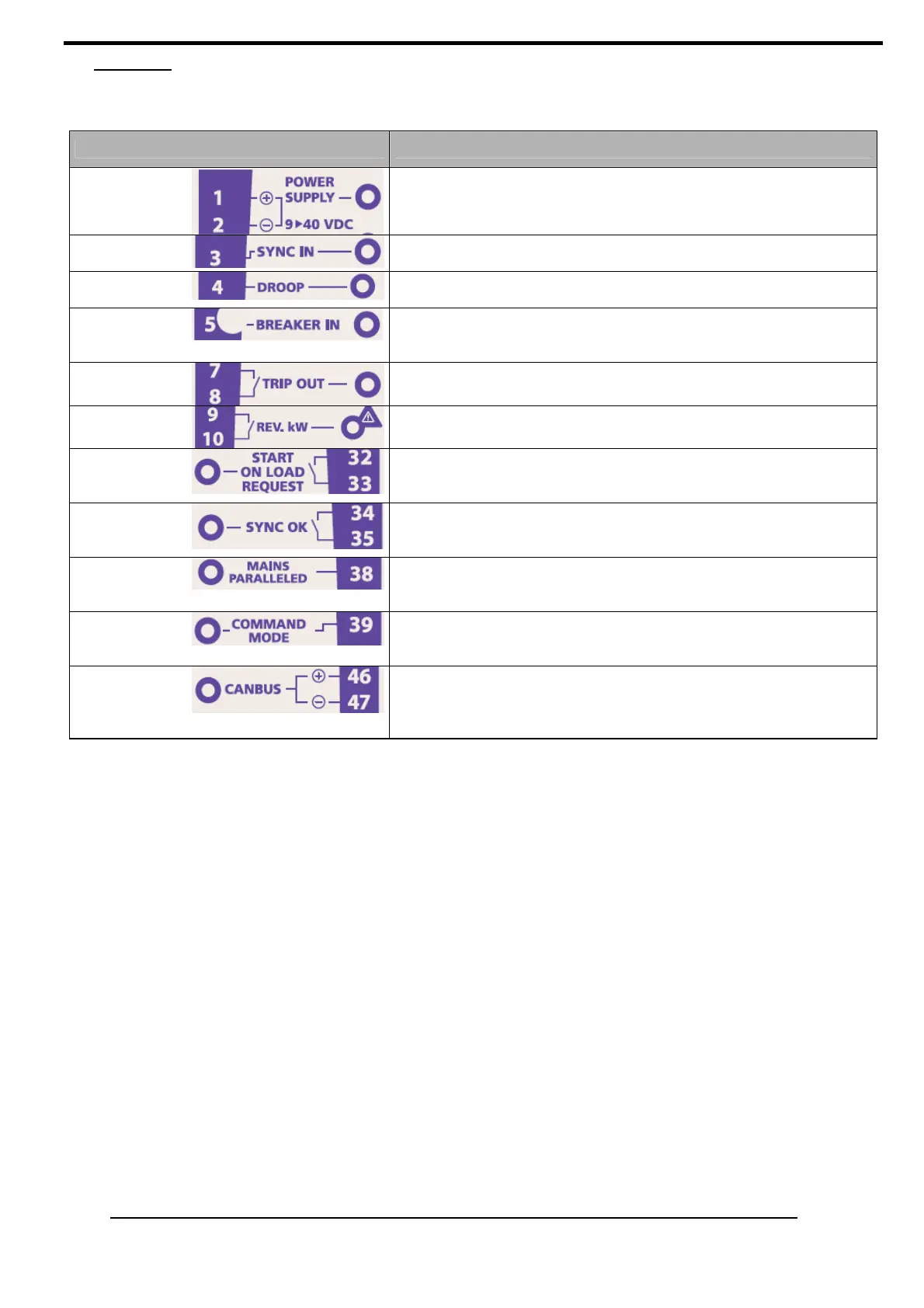
UNIGEN includes LED to have information feedback.
Led Description
POWER
SUPPLY
Green LED.
This LED is ON when DC power supply (12 or 24 VDC) is connected.
SYNC IN
This LED is ON when synchronization is required (input ‘SYNC IN’
closed to the 0Vdc)
(‘sw5’ and ‘sw6’ configuration)
.
DROOP
This LED is ON when a droop is required (input ‘DROOP’ closed to
the 0Vdc).
BREAKER IN
Green LED.
This LED is ON when the genset breaker is closed (input ‘BREAKER
IN’ closed to the 0Vdc).
TRIP OUT.
Green LED.
This LED is ON when the relay ‘TRIP OUT’ is closed.
REV KW
Red LED.
This LED is ON when the relay ‘REV Kw’ is closed.
START ON
LOAD
REQUEST
Green LED.
This LED is ON when the relay ‘START ON LOAD REQUEST’ is
closed.
SYNC OK
Green LED.
This LED is ON when the relay ‘SYNC OK’ is closed.
(‘sw5’ and ‘sw6’ configuration)
.
MAINS
PARALLELED
Green LED.
This LED is ON when the mains breaker is closed (input ‘MAINS
PARALLELED’ closed to the 0Vdc)(for Unigen Plus).
COMMAND
MODE
Green LED.
This LED is ON when a command mode is required (input
‘COMMAND MODE’ closed to the 0Vdc) (for Unigen Plus).
CANBUS
Green LED.
This LED is flickering when the load sharing mode is the canbus.
This LED flickers according to the number of Unigen communicating
in the canbus
(‘sw3’ to OFF configuration).