Please read the instructions closely before fi rst using the product. There is also a quick-start guide
on the page 8 if you need a reminder of how to use the basic functions in the future.
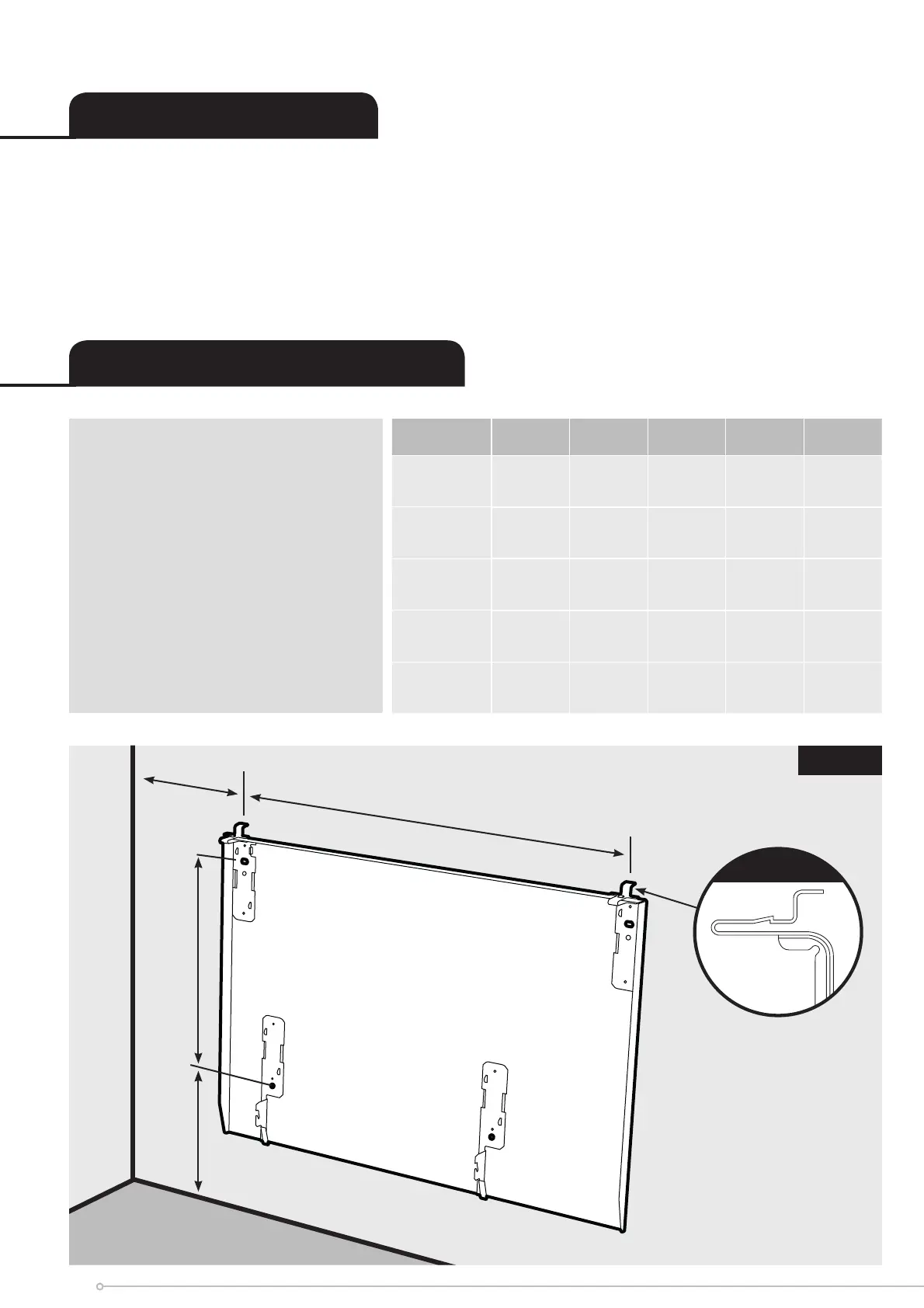
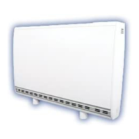
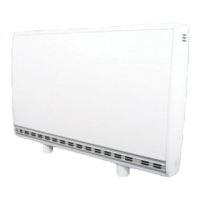
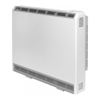
The heater is designed for wall mounting using the wall bracket supplied. It should only be operated
when in the upright position as shown - see Fig.3 and Fig.4. All models are splash proof to IP24.
Before connecting the heater check that the supply voltage is the same as that stated on the heater.
IMPORTANT - The wall bracket
supplied with the heater must
be used and the heater must
be installed in the correct
orientation. The fi xings should
be used to secure the bracket to
the particular wall on which the
heater will be installed. The heater
should be positioned observing
the minimum clearances stated
around the heater - see Fig. 1, Fig.
3 and Fig. 4.
General Information
Wall Mounting Instructions
255
‘B’
Minimum
mounting
clearance
Minimum mounting clearance
300
‘A’
MODEL A B C D E
CEP050E 390mm 150mm 503mm 536mm 104mm
CEP075E 390mm 150mm 503mm 536mm 104mm
CEP100E 560mm 150mm 671mm 536mm 104mm
CEP150E 630mm 150mm 741mm 536mm 104mm
CEP200E 800mm 150mm 911mm 536mm 104mm
Fig. 1
6