KNX Control Interface Crestron CI-KNX
4
KNX Control Interface: Crestron CI-KNX Operations & Installation Guide – DOC. 0008
Crestron CI-KNX Overall Dimensions
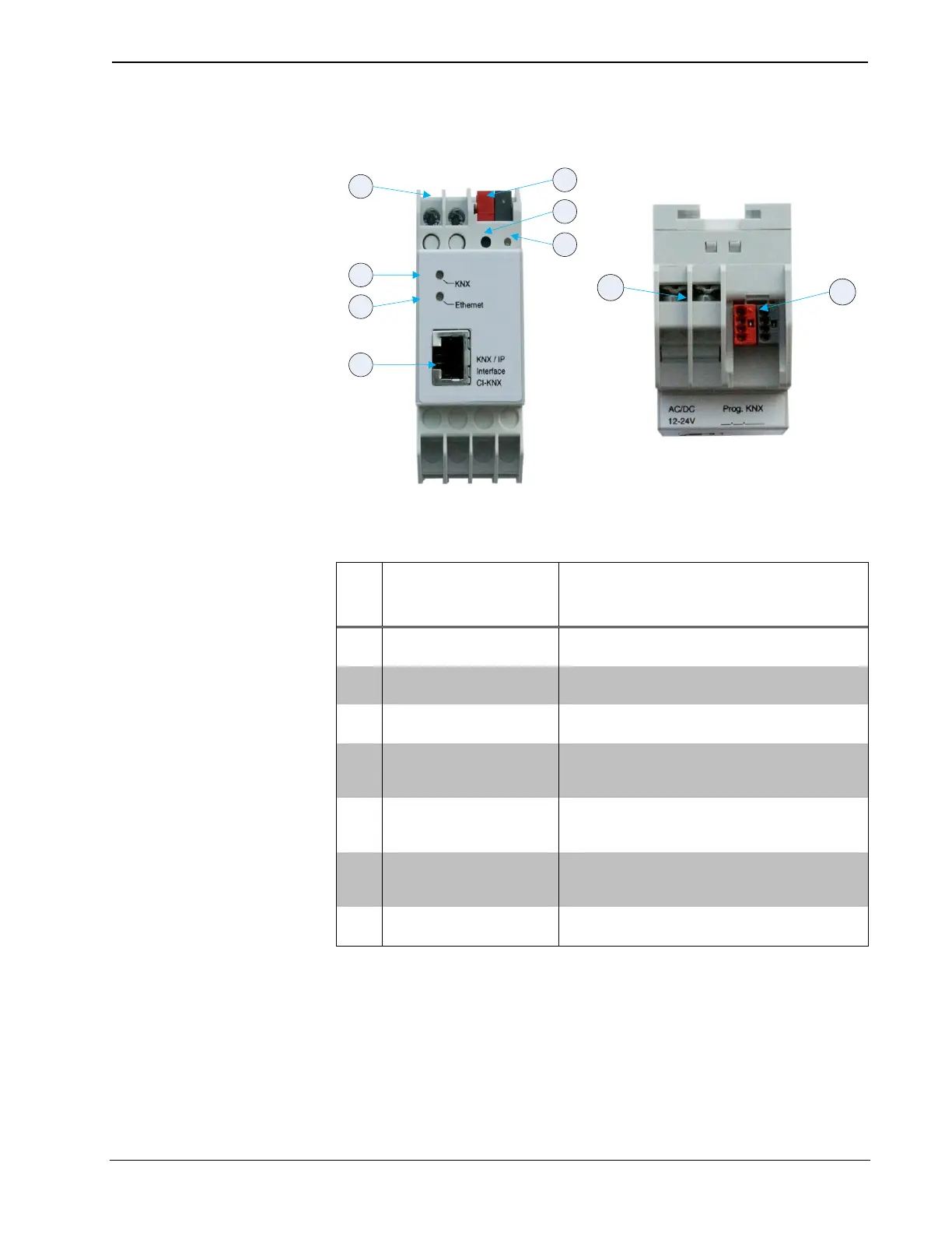
Connectors, Controls & Indicators
CONNECTORS,
CONTROLS &
INDICATORS
Connector for external power supply.
(12V to 24V AC or 12V to 30V DC)
Wago connector that connects the Creston
CI-KNX with the KNX bus.
Press to set the unit in ETS programming
mode.
Color: red
Red when the CI-KNX is in programming
mode.
Color: Green
Lights up to indicate bus voltage on KNX.
Flashes to indicate telegram traffic.
Color: Green
Lights up to indicate bus voltage on KNX.
Flashes to indicate telegram traffic.
RJ45 socket for connecting an Ethernet
patch cable.