Crestron CP3 & CP3N 3-Series Control Systems
Operations Guide – DOC. 7316C 3-Series Control Systems: CP3 & CP3N • 15
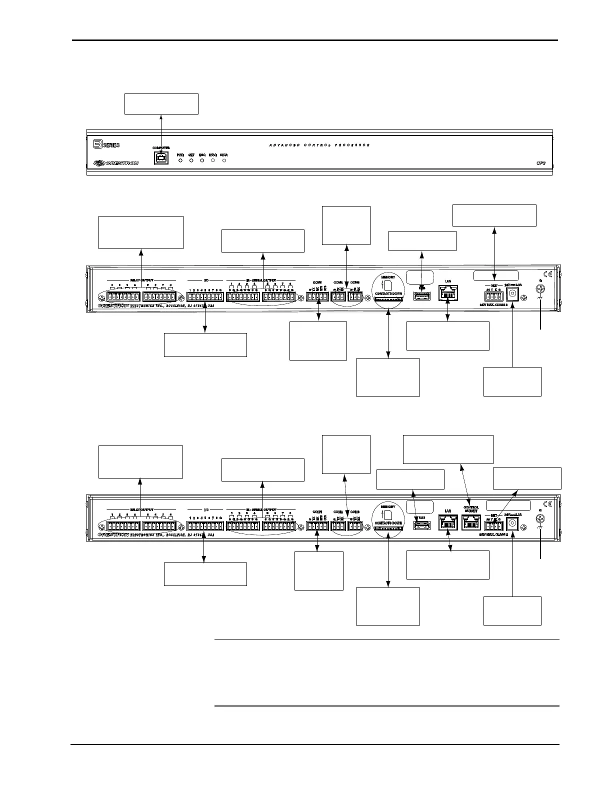
Hardware Connection for the CP3and CP3N (CP3 Shown, Front)
COMPUTER:
T
o Computer Console
Hardware Connections for the CP3 (Rear)
COM 1:
To Serial
Controlled
Devices
COM 2 & 3:
To Serial
Controlled
Devices
RELAY OUTPUT (1-8):
To Contact Closure
Devices
IR-SERIAL (1-8):
To TTL/RS-232 Devices
MEMO RY:
SD Compatible
Card Slot
LAN:
10BASE-T/100BASE-TX
Ethernet to LAN
USB:
To Storage Devices
NET:
To Cresnet Devices
24V DC, 2.0 A:
From AC Power
Pack
Ground
I/O (1-8):
To Controllable Devices
Hardware Connections for the CP3N (Rear)
RELAY OUTPUT (1-8):
To Contact Closure
Devices
IR-SERIAL (1-8):
To TTL/RS-232 Devices
COM 1:
To Serial
Controlled
Devices
COM 2 & 3:
To Serial
Controlled
Devices
MEMO RY:
SD Compatible
Card Slot
LAN:
10/100/1000BASE- T
Ethernet to LAN
24V DC, 2.0 A:
From AC Power
Pack
Ground
USB:
To Storage Devices
NE
T
:
To Cresnet Devices
I/O (1-8):
To Controllable Devices
CONTROL SUBNET:
10/100/1000BASE- T
Ethernet to Control Subnet
NOTE: Ensure the unit is properly grounded by connecting the chassis ground lug
to an earth ground (building steel).
NOTE: To prevent overheating, do not operate this product in an area that exceeds
the environmental temperature range listed in the table of specifications.