DigitalMedia Switchers Product Manual – DOC. 8418A
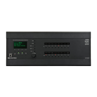
LCD Display: Green LCD dot matrix, 128 x 64 resolution adjustable LED backlight,
displays inputs and outputs by name, video and audio signal information, and
Ethernet configuration and setup menus
Soft Buttons: Push buttons for activation of LCD-driven functions
COMPUTER: USB Type B female, computer console port (6 foot [~1.8 meter]
cable included)
HW-R: Reset push button for hardware reset, reboots the switcher
ROUTE: Push button and red LED, selects Route mode to allow routing changes
VIEW: Push button and red LED, selects View mode for viewing current routes
INFO: Push button and red LED, selects Info mode for viewing audio, video, and
device information
MENU: Push button, steps menu back one level
ENTER: Push button, executes highlighted menu or value
AUDIO: Push button and red LED, selects audio routing view
VIDEO: Push button and red LED, selects video routing view
USB: Push button and red LED, selects USB routing view
Selection Knob: Continuous turn rotary knob, adjusts menu parameters
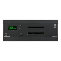
IN 1-8, 1-16, or 1-32 (model dependent): Push buttons and red LEDs, select the
corresponding input for routing
OUT 1-8, 1-16, or 1-32 (model dependent): Push buttons and red LEDs, select the
corresponding output for routing
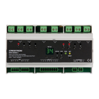
POWER SUPPLIES 1-2 or 1-3 (model dependent, RPS only): Green LEDs, indicate that
the corresponding internal power supply is functioning
POWER SUPPLIES, FAULT (RPS only): Flashing red LED, indicates a fault with an
internal power supply
NOTE: Although the switcher continues to operate if a single power supply fails, it is
recommended that the failed power supply be replaced as soon as possible to
restore power supply redundancy.

 Loading...