24 • GLS-ODT-C-CN and GLS-ODT-C-NS Product Manual — Doc. 9341A
Wiring
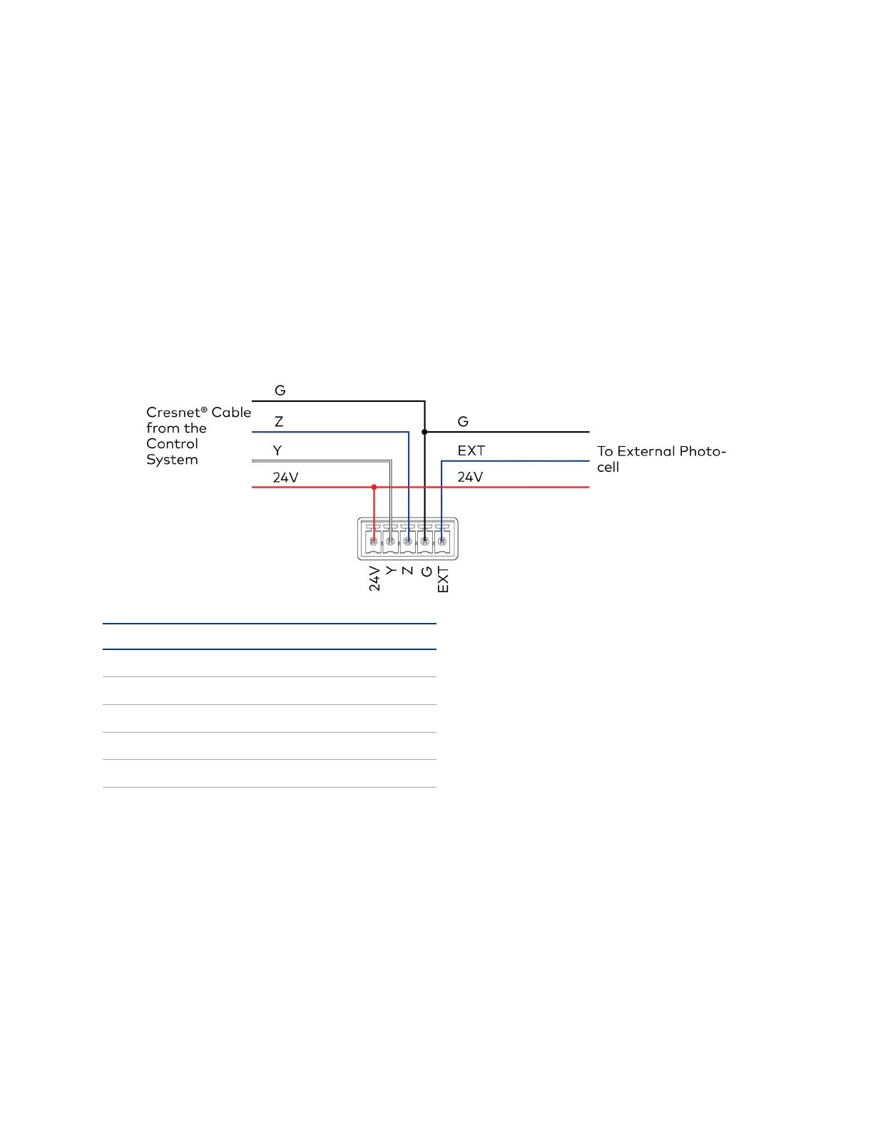
Wiring the GLS-ODT-C-CN
Connect to the Control System
Use Cresnet® cable (not supplied) to connect the control system to the GLS-ODT-C-CN. Make
connections to the 24V, Y, Z, and G ports on the GLS-ODT-C-CN.
Connect an External Photocell
Use Cresnet® cable (not supplied)to connect the GLS-ODT-C-CN to an external photocell. Make
connections to the 24V, G, and EXT ports on the GLS-ODT-C-CN.
Port Wire Color Description
24V Red Power
Y White Data
Z Blue Data
G Black Ground
EXT Blue or White 0-10VSignal
 Loading...