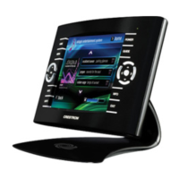
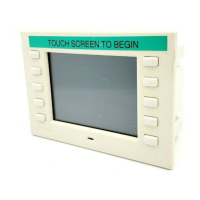
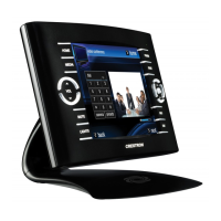
Isys™ 5.7” Wireless Touchpanels Crestron TPS-6X Series
TPS-6X Specifications (Continued)
SPECIFICATION DETAILS
Available Accessories
(Continued)
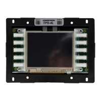
TPS-6X-DSW Wall Mount Docking Station (specify color)
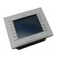
TPS-6X-FP
Button Bezel with Custom Engraving
(specify color)
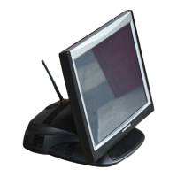
TPS-6XNL-DS-C
Desktop Docking Station, No Lock,
Charging only (specify color)
for TPS-6XNL models only
1. When IR is enabled, the RF transceiver is disabled and wired communication is restricted to console
functions only (i.e. programming and configuration).
2. Requires a wired connection via the included docking station and interface module.
3. When the battery switch on the rear of the unit has been in the OFF position, as when the unit is
shipped or stored, the TPS-6X should be placed on its docking station/charger for a minimum of four
hours before using. Refer to “Battery Switch” on page 13 for details.
4. May be powered by 24 Volts DC or Cresnet network power but not both. All power connections are
made via the included TPS-6X-IMCW interface module.
5. The latest software versions can be obtained from the Crestron
®
website. Refer to the NOTE
following these footnotes.
6. Crestron 2-Series control systems include the AV2 and PRO2. Consult the latest Crestron Product
Catalog for a complete list of 2-Series control systems.
7. When loading VisionTools
®
Pro-e (VT Pro-e) files or firmware through the RS-232 port of the control
system, be sure that the baud rate is at 38400 (Cresnet speed) or lower. Otherwise, Crestron
Toolbox™ may post the “Transfer Failed” message.
8. Text engraving is not backlit on white models.
NOTE: Crestron software and any files on the website are for authorized Crestron
dealers and Crestron Authorized Independent Programmers (CAIP) only. New users
may be required to register to obtain access to certain areas of the site (including the
FTP site).
8 • Isys™ 5.7” Wireless Touchpanels: TPS-6X Series Operations Guide – DOC. 6875B
 Loading...