EasyManua.ls Logo

Crestron TS-1070-B-S User Manual

Crestron TS-1070-B-S
8 pages
To Next Page IconTo Next Page
Page #1 background imageLoading...
Page #1 background image
The Crestron Flex Wall Mount UC Video Conference System for Zoom
Rooms™ software (UC-B160-Z) delivers a powerful, professional
solution for knowledge workers who want the Zoom Rooms software
experience in small to midsize meeting and conference rooms.
MinimumRequirements
l
A video display, connected to the UC-ENGINE-Z.The system
supports a second display if desired.
l
A Zoom Rooms account or activation code
View the Crestron Flex Pre-Deployment Checklist to help plan your
Crestron Flex installation.
In the Box
UC Engine Bracket Assembly
1 UC-BRKT-100-Z-ASSY (6511049)
1 Power cord
Mounting Hardware
UC Video Conference Smart Soundbar
1 UC-SB1-CAM-FLEX (6511046)
1 Power Cord
1 USBCable
Mounting Hardware
Tabletop Touch Screen Device
1 TS-1070-B-S (6510821)
Accessories
1 PWE-4803RU, PoEInjector (6502429)
2 CBL-CAT5E-7, CAT5e cable, RJ-45-to-RJ-45, Black,
7 ft (2.1 m) (6509924)
1 CBL-HD-THIN-HS-6, Thin HDMI® cable,
6 ft (1.8 m) (6510946)
1 CBL-HD-20, HDMI cable, 20 ft (6.1 m) (6503567)
1 CBL-USBC-HD-9, USB 3.0 to HDMI Converter cable,
9 ft (2.7 m) (6510718)
1 DM-CBL-ULTRA-PC-20, DigitalMedia™ Ultra Patch
cable,
20 ft (6.1 m) (6507640)
1
UC-B160-Z
QuickStart
Crestron Flex Wall Mount UC Video Conference System for Zoom Rooms™ Software
Question and Answer IconNeed help?

Do you have a question about the Crestron TS-1070-B-S and is the answer not in the manual?

Crestron TS-1070-B-S Specifications

General IconGeneral
BrandCrestron
ModelTS-1070-B-S
CategoryConference System
LanguageEnglish

Summary

System Overview and Connections

System Connection Diagram

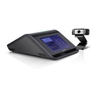
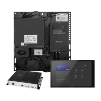
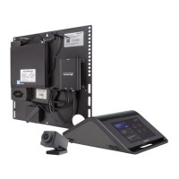
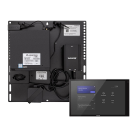
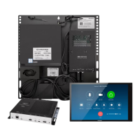
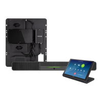
Illustrates standard system connections for the UC-B160-Z, including the diagram and component placement.

Connecting the System Components

Initial Component Connections

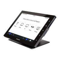
Make connections to the TS-1070-B-S and remove connector covers on the UC-BRKT-100-Z-ASSY.

Completing the Installation

Securing Connector Covers

Secure connector covers using a Phillips head screwdriver and optional spanner screws for added security.

System Configuration

Applying Power to the System

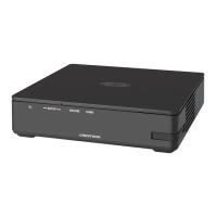
Power on the UC-ENGINE-Z and other devices; the display will show a pairing code for setup.

Logging into Zoom Rooms Service

Sign in to the Zoom Rooms service using an activation code or credentials via the touch screen.

Advanced System Configuration

Connect a USB keyboard/mouse to the UC-ENGINE-Z for configuring system features.

Visiting the Product Page

Accessing Product Information

Scan the QR code or visit the provided URL to access the product page and related details.

Additional Product Information

Legal and Warranty Information

Information on software licensing, product warranty, patents, and open source software details.

Related product manuals