15
• Clean the battery and device contacts as
needed and before inserting.
• Do not expose the batteries to extreme condi-
tions (e.g. radiators or direct sunlight). Other-
wise there is an increased risk of leakage.
• Batteries can be life-threatening if swallowed.
Therefore, store batteries in a place inac-
cessible to small children. Medical attention
must be sought immediately if a battery is
swallowed.
Danger!
• Handle damaged or leaking batteries with
extreme caution and dispose of them properly
as soon as possible. Wear gloves when doing
so.
• If you come into contact with battery acid,
wash the affected area with soap and water.
If battery acid gets in your eye, rinse it with
water and seek medical attention immediately!
• The connection terminals must not be short-cir-
cuited.
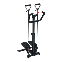
Assembling the stepper
Step 1 (Fig. B)
1. Place the stepper (1) with the bottom side up
on a flat and level surface.
2. Insert the plastic back feet (2) and (3) into the
frame of the stepper (1) as shown in Fig. B.
The rippled surfaces of the plastic back feet
(2) and (3) are facing upward and the point-
ed ends are facing backward.
3. Place the plastic front feet (4) onto the frame
of the stepper (1) as shown in Fig. B. The
wheels of the plastic front feet (4) are facing
upward and forward.
4. Fasten each of the plastic back feet (2) and
(3) with one screw (18) and each of the plas-
tic front feet (4) with one screw (17).
Note: make sure that the pre-drilled holes in the
frame and in the plastic feet line up.
Step 2 (Fig. C)
1. Connect the top (6) and bottom (5) support
poles.
Note: ensure that the screw holes are correctly
aligned.
2. Select one of the four holes on the top support
pole (6) and fasten the connection with the
setting screw (13).
Step 3
1. Lead the cable (8a) of the computer (8)
through the holder (7) and place the comput-
er in the holder (Fig. D).
Note: make sure that the computer is correctly
positioned in the holder and that the cable does
not get caught on anything.
2. Lead the cable (8a) of the computer through
the grab poles so that a section of the cable is
hanging out below (Fig. E).
3. Place the holder (7) into the top grab pole (6)
(Fig. E).
4. Fasten the holder to the top grab pole (6) with
the screw (19) (Fig. E).
Step 4 (Fig. F)
1. Turn the stepper (1) back over and connect
the end of the cable (1a) of the stepper (1) to
the end of the cable (8a) of the computer (8).
2. Lead the connected cables into the bottom
opening (1b) of the stepper.
Note: make sure that the cables do not get
caught in the process.
Step 5 (Fig. G)
1. Place the grab poles into the stepper.
Note: ensure that the screw holes are correctly
aligned.
2. Fasten the support poles to the front of the
stepper with two screws (16) and to the back
of the stepper with one screw (16).
3. Turn the adjusting screw (12) into the thread
on the front of the stepper.
Note: you can use the adjusting screw to set the
step height of the pedals.
To increase the step height, turn the adjusting
screw in a clockwise direction.
To reduce the step height, turn the adjusting
screw anti-clockwise.
Step 6 (Fig. H)
1. Place the handle (9) with the cover (11) onto
the top support pole (6).
2. Attach the handle with the cover with two
screws (15) and two washers (20).
GB