119
• Seizedordisconnectedboilerpump
• BlownPumpFuse
Supply Sensor – The boiler control infers the supply temperature based on the resistance measured at the supply sensor. Table
14.6ashowsthisresistanceasafunctionofwatertemperature.Becausethecontrol/supplysensorisusedastheboiler’swater
temperature limit control, there are actually two “thermistors” in the supply sensor wired in parallel (Figure 10.5). The control
comparestheresistancesacrossthesetwothermistorsandpreventsboileroperationifthereisasignicantdifferencebetweenthe
readings.
Return Sensor – The boiler control infers the return temperature based on the resistance measured across a single thermistor in
the return sensor. Table 14.6a shows this resistance as a function of water temperature.
Flue Temperature Sensor–Theboilercontrolinferstheuegastemperaturebasedontheresistancemeasuredattheue
temperaturesensor.Table14.6ashowsthisresistanceasafunctionofuetemperature.Thereareactuallytwo“thermistors”in
theuetemperaturesensorwiredinparallel(Figure10.5).Thecontrolcomparestheresistancesacrossthesetwothermistorsand
preventsboileroperationifthereisasignicantdifferencebetweenthereadings.
Outdoor Sensor – The boiler control infers the outdoor temperature based on the resistance measured across a single thermistor
in the outdoor sensor. Table 14.6b shows this resistance as a function of temperature.
Condensate Trap–Thecondensatetrapallowscondensatetoleavetheboilerwhilecontaininguegasses.Intheeventthat
this trap becomes blocked, condensate will start to back up in the trap. To prevent a rising condensate level from backing up
intotheheatexchanger,bothagroundwireandtheamerodwirearebondedtothistrapinsuchawaythatanabnormallyhigh
condensatelevelwillconductamecurrentdirectlytoground(Figure10.5).Theboilercontrolwillinterpretthisasalossof
ameandenterasoftlockout.SeeFigures7.35or13.3fortraplocation.
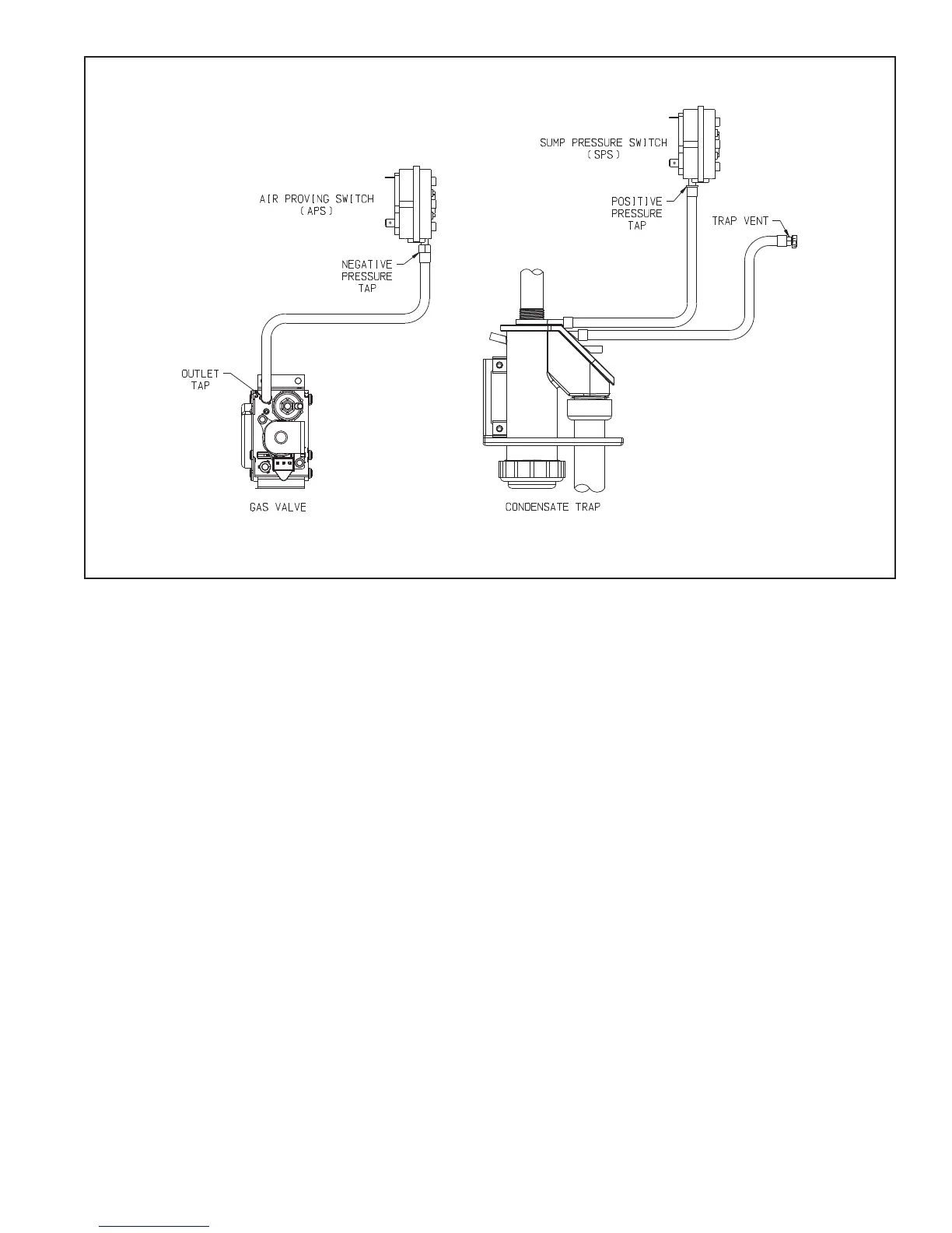
FIGURE 14.5: PRESSURE SWITCH TUBING CONNECTIONS