65
B. Near Boiler Piping Design
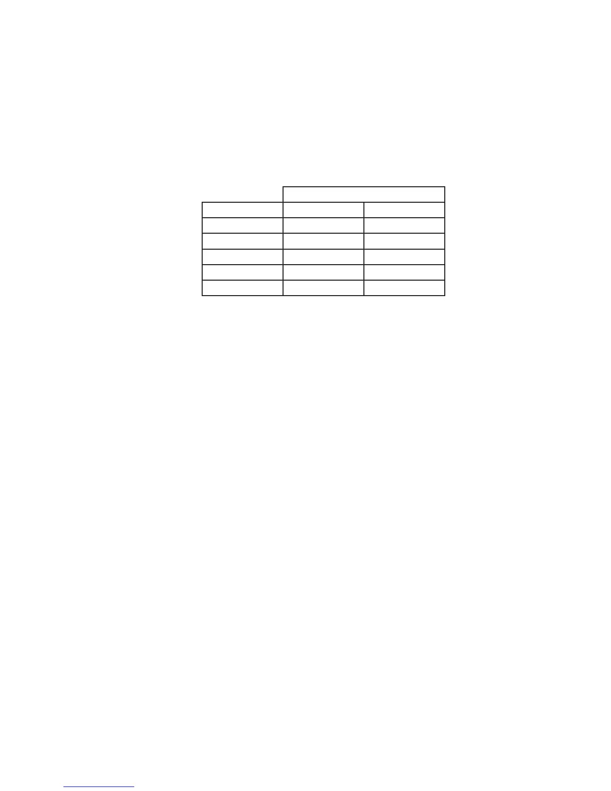
ProperoperationofthisboilerrequiresthatthewaterowratethroughitremainwithinthelimitsshowninTable
9.1anytimetheboilerisring.Atowratesbelowtheminimumshown,theboiler’sowswitchand/ortemperature
riselimitfunctionmaypreventtheboilerfromring.Flowratesthroughtheboilerinexcessofthemaximumshownin
Table 9.1 can result in excessive noise or erosion damage to piping
There are two basic methods that can be used to pipe this boiler into the system. Method #1 (primary-secondary
piping) is always preferred. Additional information on hydronic system design can be found in the I=B=R Guide RHH
published by the Air-Conditioning, Heating and Refrigeration Institute (AHRI).
Table 9.1: Flow Limitations
Flow (GPM)
Model Minimum Maximum
80MBH 5.0 13.3
100MBH 5.1 13.3
120MBH 6.2 13.3
150MBH 7.7 13.3
180MBH 9.3 13.3
Method 1: Primary/Secondary Piping (Strongly Recommended)
This method can be used in heat-only applications as shown in Figure 9.2 or with an indirect water heater as shown
inFigure9.3AorFigure9.3B.Inthissystem,theowratethroughtheboiler(“secondaryloop”)iscompletely
independentoftheowratethroughthesystem(“primaryloop”).Usethefollowingguidelinestoensurethattheboiler
willhavetherequiredowshowninTable9.1regardlessoftheowintheheatingsystem.
1)SystemLoopPiping-Sizethesystemcirculatorandpipingtoobtainthedesignowratethroughtheheatingsystem
as you would on any other heating system. All piping between the expansion tank and secondary connection tees must
beatleast1”.Inordertokeeptheowratesinthesystemandboilerloopsindependentofeachother,provideatleast
8diametersofstraightpipeupstreamoftherstteeand4diametersdownstreamofthesecondtee.Keepthedistance
betweentheexpansiontankandtherstsecondaryteeasshortaspractical.
2)BoilerLoopPiping–AllboilersaresuppliedwithabuiltincirculatorwhichwilldelivertheowrequiredbyTable
9.1 provided both of the following conditions are met:
• Allpipingintheboilerloophasanominalsizeofatleast1”
• Theequivalentlengthofallpipingintheboilerloopis60ftorless.
To verify that the 60ft, equivalent length is not exceeded, do the following:
a) Countallttingsintheplannedboilerloop(theshadedpipinginFigure9.6).Indoingso,donotcountthe
secondaryconnectiontees,unions,orthettingssuppliedwiththeboiler(thesehavealreadybeenaccountedfor).
b) UsingTable9.4,ndtheequivalentlengthsofallttingsinthesecondaryloop.Totaltheseequivalentlengthsand
add them to the total length of planned straight pipe in the secondary loop.
c) The result is the total equivalent length of the planned boiler loop. If the equivalent length calculated in (b) is under
thelimitshowninTable9.5,theboilerpumpwillachieveaowrateandtemperatureriseapproximatelyequaltothat
shown in this table. Otherwise, the equivalent length must be reduced.