46
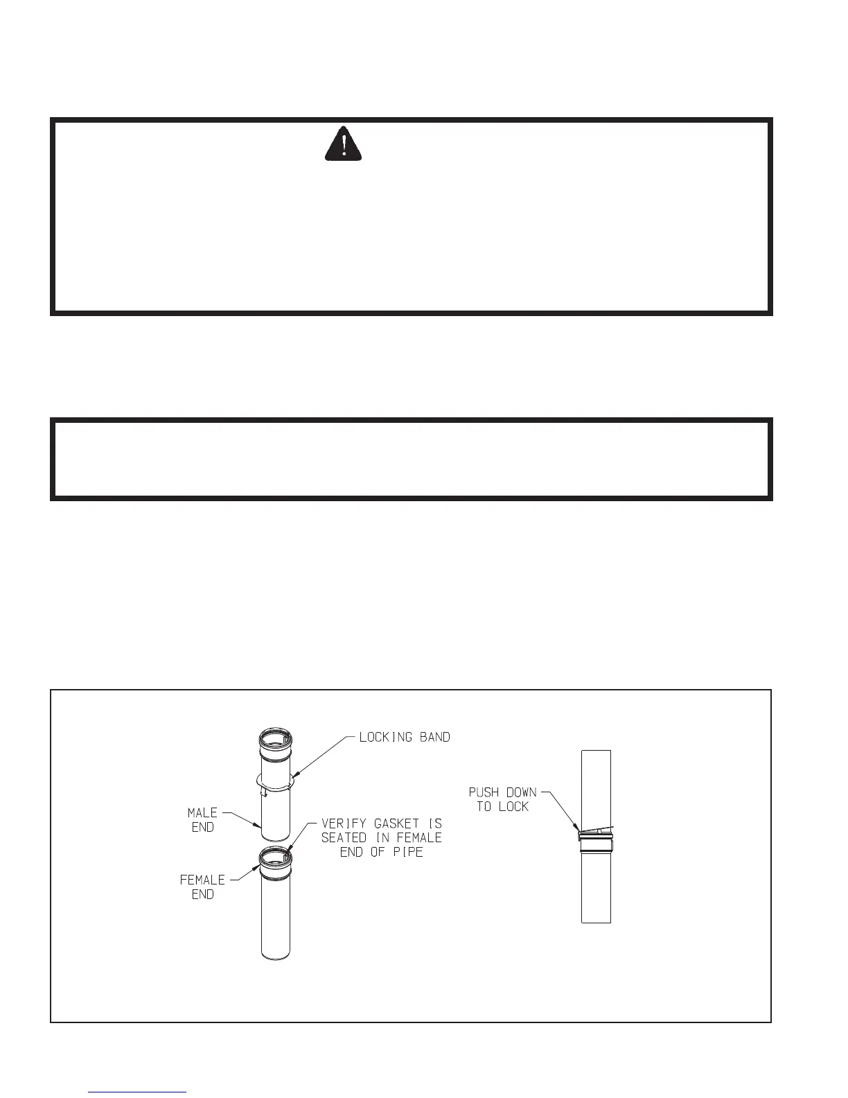
FIGURE 7.35: POLYPRO LOCKING BAND INSTALLATION
F. Assembly of DuraVent PolyPro Vent Systems
1. This boiler has been approved for use with the DuraVent PolyPro single wall polypropylene vent system to be provided
by the installer.
2. Assemble the vent system, starting at the boiler:
a. The vent adaptor has two different inside diameters. The smaller, lower, inside diameter accepts 3” nominal PolyPro
(Figure 7.27). A locking ring in the adaptor prevents the vent pipe from coming out of the adaptor once it is inserted.
Lubricatetheuppergasketintheventadaptorwithsoapywaterandinserttherstpieceof3”PolyProintothe
adaptor until it bottoms out.
b. If2”Polyproistobeusedfortheventsystem,reducetherstpieceof3”PolyproinstalledinStep(a)to2”using
DuraVent # 3PPS-R2. Otherwise assemble the next piece of 3” Polypro.
c. For each joint, verify that the gasket is evenly seated in the bell (female) end of the pipe. Lubricate this gasket with
water. Slide a locking band over the male end of the pipe to be joined as shown in Figure 7.35. Push the male end
of the next section of pipe into the bell until it bottoms out, then back out 1/4-5/8” to provide room for thermal
expansion.PushbarbonlockingbandoverthebellendoftherstsectionofpipeasshowninFigure7.35.
d. Assembletherestoftheventsystemperthemanufacturer’sinstallationinstructions,beingsuretopitchhorizontal
sections back towards the boiler 5/8” per ft.
e. Support each horizontal pipe section with a minimum of one wall strap each and at intervals not exceeding 4ft.