55
H. Assembly of Centrotherm Innoue Vent Systems
1. ThisboilerhasbeenapprovedforusewiththeCentrothermInnouesinglewallpolypropyleneventsystemtobe
provided by the installer.
2. Assemble the vent system, starting at the boiler:
a. Theventadaptorhastwodifferentinsidediameters.Thesmaller,lower,insidediameteraccepts3”nominalInnoue
(Figure 7.27). A locking ring in the adaptor prevents the vent pipe from coming out of the adaptor once it is inserted.
Lubricatetheuppergasketintheventadaptorwithwaterandinserttherstpieceof3”Innoueintotheadaptor
until it bottoms out.
b. If2”Innoueistobeusedfortheventsystem,reducetherstpieceof3”InnoueinstalledinStep(a)to2”using
Centrotherm#ISRD0302.Otherwiseassemblethenextpieceof3”Innoue.
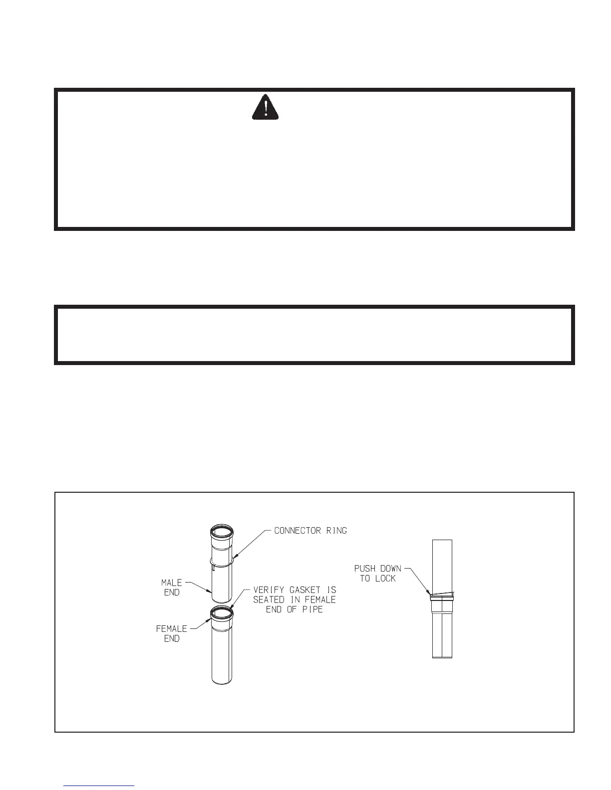
c. For each joint, verify that the gasket is evenly seated in the bell (female) end of the pipe. Lubricate this gasket with
Centrocerin # IACE50. Slide a connector ring over the male end of the pipe to be joined as shown in Figure 7.44.
Push the male end of the next section of pipe into the bell until it bottoms out, then back out 1/4” to provide room
forthermalexpansion.PushhookonconnectingringoverthebellendoftherstsectionofpipeasshowninFigure
7.44.
d. Assembletherestoftheventsystemperthemanufacturer’sinstallationinstructions,beingsuretopitchhorizontal
sections back towards the boiler 5/8”/ft.
e. Support each horizontal pipe section with a minimum of one wall strap each and at intervals not exceeding 39in.
FIGURE 7.44: INNOFLUE CONNECTOR RING INSTALLATION