40
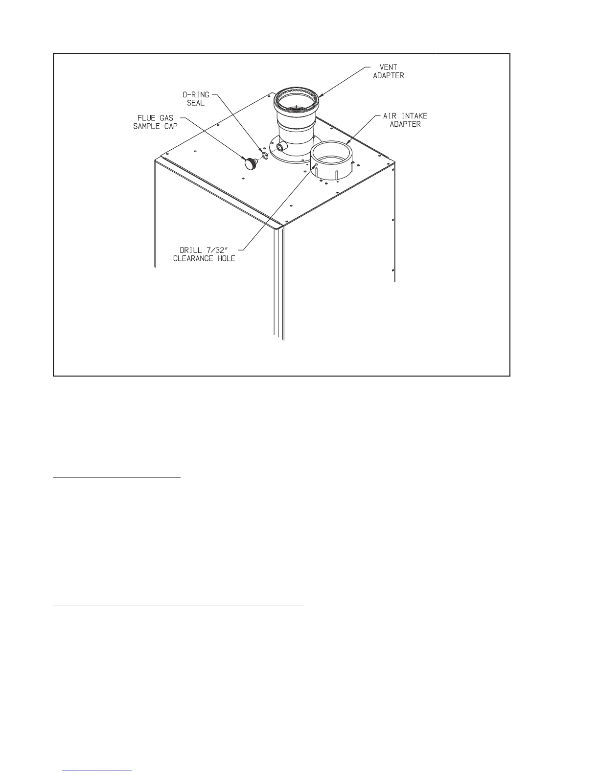
FIGURE 7.27: VENT CONNECTIONS AND FLUE GAS SAMPLE CAP LOCATION
g. Assemble the rest of the vent system, being sure to pitch horizontal sections back towards the boiler 1/4”/ft. Support
the vent at intervals not exceeding 4ft.
h. Maintain the clearances from the vent pipe outlined in Part VII-A of this manual. If exiting the exterior wall using
PVC pipe, use half of an appropriately sized wall thimble (or a sheet metal plate) on the exterior of the building, to
provide a weather tight seal while maintaining the proper clearance in the wall penetration. Seal the joint between
the pipe and the wall plate using RTV applied on the exterior side of the wall. This sealant must not restrain the
expansion of the vent pipe.
3. Installation of Air Intake System - Start assembly of the PVC air intake system at the boiler. Assembly of the air intake
system is done in the same manner as the vent system except as follows:
a. Drilla7/32”clearanceholeintothefrontsideoftheairintakeadapter.InserttherstpieceofPVCairintakepipe
into the air intake connection and drill a 1/8” tap hole into the PVC which lines up with the 7/32” clearance hole and
secure them together with a #10 x 1” sheet metal screw. Seal the joint between the intake pipe and the adaptor with
RT V.
b. All intake piping may be PVC.
c. There is a 0” minimum clearance between the air intake piping and all types of construction.
d. To the extent possible, pitch horizontal air intake piping towards the outdoors.
4. Installation of Horizontal Fitting Terminals (Terminal Option A):
a. See Figure 7.28 for proper orientation of twin pipe horizontal terminals. Outer edge of both terminals must be
within 10” from wall surface. (Figure 7.6)
b. Ifdesired,theterminalscanbeattachedtotheendoftheventand/orintakepipeswitheldsuppliedstainlesssteel
screws so that they can be later removed for cleaning and inspection. If this is done, drill a clearance hole in the
coupling or elbow and a tap hole in the end of the vent/intake pipes to accept these screws.
c. If these terminals are installed on snorkels, assemble the snorkels as shown in Figure 7.12. Brace the vertical run of
piping on the building exterior as required.