69
Example – A 120MBH model is to be connected to a heating system as shown in Figure 9.6. A total of 20 ft of straight pipe
will be installed between the boiler and the system loop.
Countallttingsintheboilerloop(shadedinFigure9.6):
3 90 Elbows
2 Turn in Tee (under boiler- primary-secondary tees not counted)
2 Isolation Valves
1 Y Strainer having a Cv of 30.
Note:Unions,SecondaryConnectionTees,andfactorysuppliedttingsareignored.
Calculate total equivalent length from Table 9.4:
20ft Straight Pipe + 3 Elbows x 2.8 + 2 Turn in Tee x 5.5 + 2 Valves x 0.7 = 40.8 Equivalent Feet
Sincethetotalequivalentlengthislessthan60ft,owthroughboilerloopmeetsrequirementsinTable9.1
3) Indirect Water Heater Loop Piping – If an indirect water heater is used, install it as shown in Figures 9.3A or 9.3B. The
piping shown in Figures 9.3A and 9.3B is functionally identical. Use the variation that is most compatible with the existing
piping on the job. Refer to the indirect water heater installation manual for the proper sizing the indirect water heater loop
pump and piping.
4) Hydraulic Separators – Hydraulic separators serve the same purpose as the closely spaced tees connecting the boiler and
system loops in Figure 9.1. They also generally provide effective connection points for automatic air elimination devices
and an expansion tank. These separators are available from several sources and may be used in place of the closely spaced
tees shown in Figures 9.2, 9.3A or 9.3B. When a hydraulic separator is used in place of the tees, the 60ft equivalent length
limitationstillapplies.Selectahydraulicseparatorhaving1”orlargerboilerconnectionsthatisdesignedfortheboilerow
rates shown in Table 9.1.
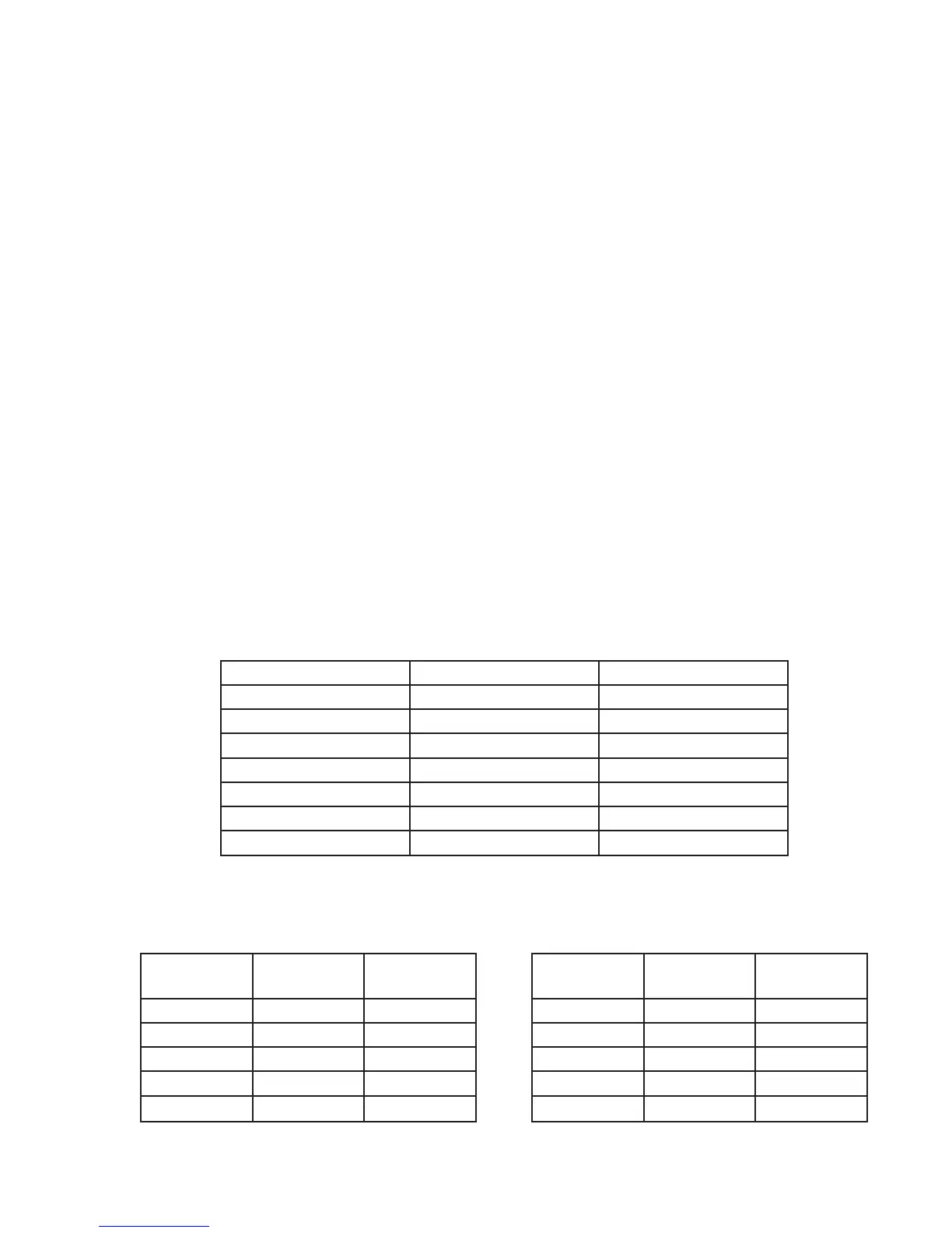
Table 9.4: Equivalent Lengths for Selected Valves and Fittings
(May Be Used for Copper or Threaded Fittings)
Fitting Pipe Size Equivalent Length (ft)
90° Elbow 1” 2.8
45° Elbow 1” 1.4
90° Turn in Tee 1” 5.5
Run of Tee 1” 1.8
Gate Valve (Open) 1” 0.7
Full Port Ball Valve 1” 0.7
Y-Strainer* 1” 7.0
* Based on Cv of 20. Pressure drop through strainers varies widely. 7ft equivalent length may be
assumed for strainers having a published Cv greater than 20.
Table 9.5a: Flow Available with Boiler
Loop Equivalent Length of 30ft or Less*
Table 9.5b: Flow Available with Boiler
Loop Equivalent Length of 60ft or Less*
Boiler Model
Approx. Flow
(GPM)
Approx. Rise
(°F)
Boiler Model
Approx. Flow
(GPM)
Approx. Rise
(°F)
80MBH 7.5 19 80MBH 7.3 20
100MBH 8.3 22 100MBH 8.0 23
120MBH 9.6 22 120MBH 9.2 24
150MBH 12.9 21 150MBH 11.9 23
180MBH 12.9 25 180MBH 11.9 27
* For multi-speed pumps, these tables assume pump is set to highest speed.