77
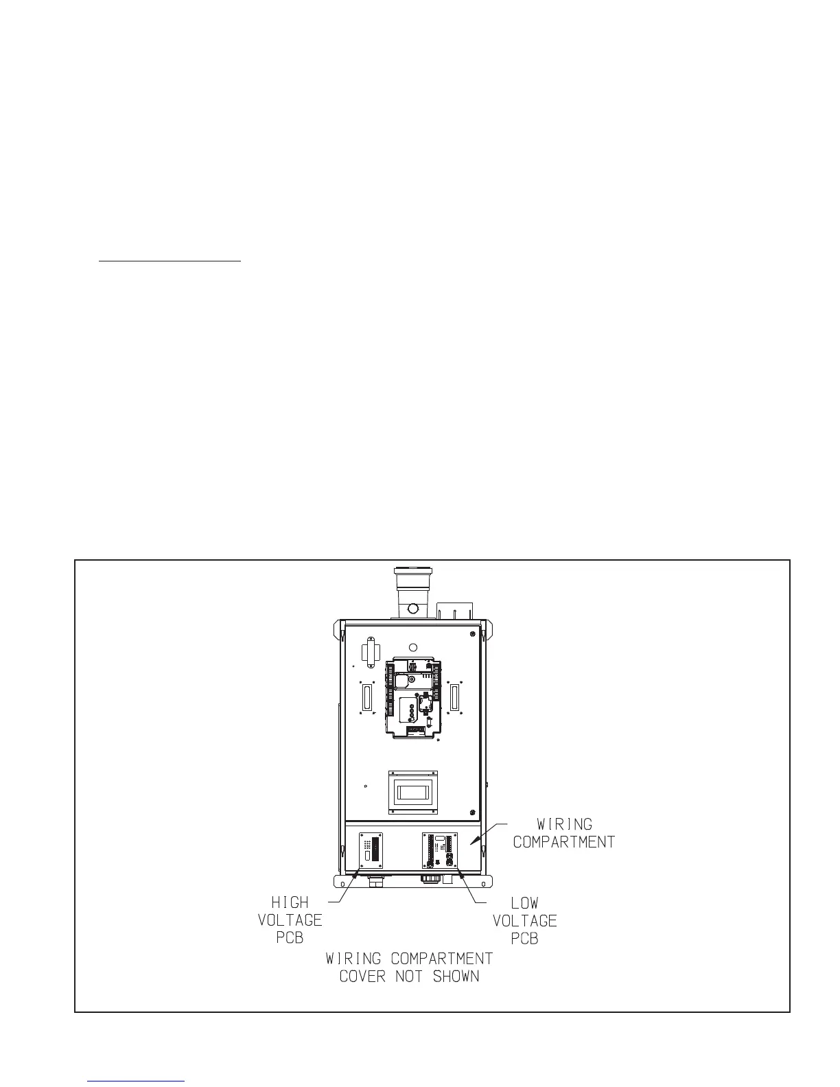
FIGURE 10.1: LOCATION OF HIGH AND LOW VOLTAGE PRINTED CIRCUIT BOARDS (PCB)
The use of the pump outputs are as follows:
a) System Pump - Pumps water through the radiation. This pump is hydraulically separated from the boiler pump, either by
closely spaced tees, or by a hydraulic separator. The system pump is always on when the system is responding to a call
forCH.DependingontheDHWconguration,itmayalsobeonduringacallforDHW.
b) DHW Pump (“IWH Circulator”) - Pumps water directly through the indirect water heater.
Maximum combined current draw for all circulators is 6.3 FLA. See Section XII of this manual for information on setting up
the pump operation.
2) Low Voltage Connections–LowvoltageeldconnectionsonthelowvoltagePCBareshowninFigure10.3andarelisted
from top to bottom:
• HeatT’Stat-24VACheatingthermostat(R-24V“Hot”)
• HeatT’Stat-24VACheatingthermostat(W-EnergizedorCallforHeat)
• HeatT’Stat-24VACheatingthermostat(C-24VCommon)
• DHWStat-24VACdomestichotwaterthermostat(1)
• DHWStat-24VACdomestichotwaterthermostat(2)
• ExternalLimit-Fieldsuppliedlowvoltagesafetylimitcontacts(1)
• ExternalLimit-Fieldsuppliedlowvoltagesafetylimitcontacts(2)
• AlarmContact(1)
• AlarmContact(2)
• EnviraCOMDevice(D)
• EnviraCOMDevice(R)
• EnviraCOMDevice(C)