86
10) If the boiler is to be converted to propane (LP gas) or used at altitude above 2000ft, start-up and adjust throttle as described in
Appendix A.
11) Start the boiler using the lighting instructions on page 90. With the boiler powered up, and with no call for heat, the display
should look like Figure 11.2a. Once a call for heat is present, it will look like Figure 11.2b.
12) Theboilershouldattempttoreapproximately30secondsafteracallforheatappears.Withtheupperfrontcoverremoved
from the boiler, this try for ignition will appear as an audible spark (lasting approximately 4 seconds) and an audible click
fromthegasvalve.Uponinitialstart-up,thegastrainwillbelledwithair.Evenifthegaslinehasbeencompletely
purgedofair,itmaytakeseveraltriesforignitionbeforeaameisestablished.Iftheboilerdoesnotlightafterfourtries
for ignition, it will enter a “soft lockout” and will wait for one hour before attempting another ignition sequence. This soft
lockoutcanberesetbyinterruptingpowertotheboilerforafewseconds.Onceaamehasbeenestablishedfortherst
time,subsequentcallsforburneroperationshouldresultinaameonthersttry.
13) Ifthereisaproblemthatappearsbeforethersttryforignition,oriftheboilerfailstolightaftervetriesforignition,the
ashing“ActiveFault”buttonwillappearontheHomescreen(Figure 11.2c). Touching this button will take the user to the
Diagnosticsmenuwherethecauseoftheproblemcanusuallybefoundbypressingtheashingbuttononeachsuccessive
screen. For more information, see Section XIV of this manual.
14) Inspecttheamevisiblethroughthewindow.Onhighretheameshouldbestableandmostlyblue(Fig.11.3).Noyellow
tippingshouldbepresent;however,intermittentecksofyellowandorangeintheamearenormal.
15) Check the inlet gas pressure. Verify that the inlet gas pressure is between the upper and lower limits shown on the rating
plate with all gas appliances on and off.
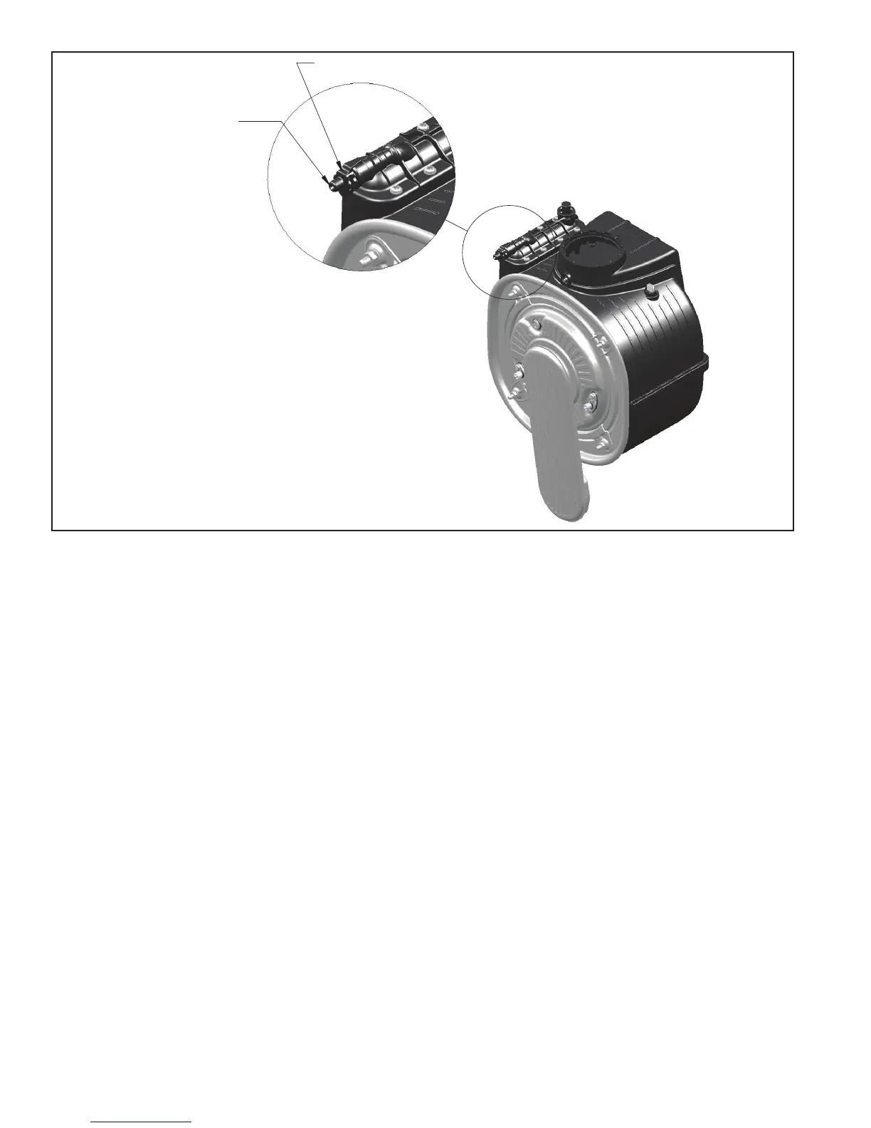
BEFORE OPENING VENT.
ATTACH 1/4" ID CLEAR
TUBING TO HOSE BARB
AND ROUTE TO SAFE PLACE
AWAY FROM CONTROLS
MANUAL AIR VENT
FIGURE 11.1: LOCATION OF MANUAL AIR VENT