CE 4000 Service Manual
Specifi cations 2-2
130485-1 Rev. B
©2002 Crown Audio, Inc.
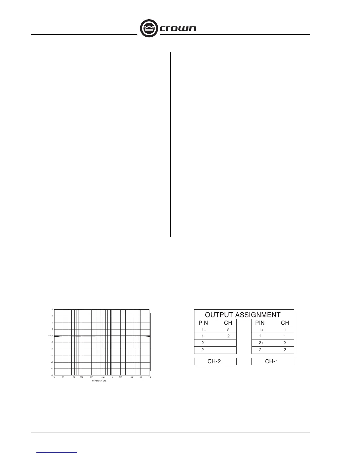
Figure 2.1 Typical Frequency Response
Fault: Normally off, this red indicator will blink under
fi ve different conditions:
1. When the amplifi er is fi rst powered up, until the
unit is ready for operation.
2. If the heatsinks reach a temperature above
normal working limits.
3. If the transformer thermal protection circuit is
activated.
4. If amplifi er output wires develop a short-circuit.
5. If the amplifier output stage becomes non-
operational.
6. If there is a problem elsewhere in the amplifi er.
This circuit may be monitored remotely by plugging
a simple switching circuit using an LED or other
signaling device into the back-panel RJ-11 (Fault)
jack. Under some conditions, the output of the
amplifi er will be muted.
Power: A green LED that turns on when the amplifi er
has been turned on and has power.
Input/Output
Input Connector (standard module): One Neutrik®
Combo connector for each channel which features
a balanced ¼-inch (6.35-mm) phone jack and a
3-pin female XLR connector, in parallel with a barrier
strip termination.
Input Stage: Input is electronically balanced and
employs precision 1% resistors.
Input Impedance: Nominally 20 k ohms, balanced.
Nominally 10 k ohms, unbalanced.
Input Sensitivity: 0.775 volts or 1.4 volts for standard
1-kHz power, or fi xed 26-dB gain.
Output Connectors: Three options available: Four
(4) Neutrik® Speakon® NL4MP (mates with NL4FC)
output connectors; (2) 5-way binding posts in parallel
with two (2) Speakon® connectors; or barrier strip
outputs in parallel with two (2) 5-way binding posts.
Output Signal,
Stereo: Unbalanced, two-channel;
Bridge-Mono:Balanced, single-channel. Channel
1 controls are active; Channel 2 should be turned
down.
Wiring Confi guration: (see Figure: 2.2).
Protection
CE 4000 amplifi ers are protected against shorted,
open or mismatched loads; overloaded power
supplies; excessive temperature, chain destruction
phenomena, input overload damage and high-
frequency blowups. They also protect loudspeakers
from input/output DC, large or dangerous DC offsets
and turn-on/turn-off transients.
Construction
Rugged steel chassis is formed into a durable
package any stagehand could love. Coated with
environmentally friendly powder for long life and
ease of maintenance.
Cooling: Three-speed proportional speed fan.
Dimensions: EIA Standard 19-inch rack mount width
(EIA RS-310-B), 5.25-inch (13.34-cm) height and
16.25-inch (36.56-cm) depth with additional 1-inch
rear rack ears.
Weight: The CE 4000 net weight is 33.3 pounds (15.1
kg). Shipping weight is 39.3 pounds.
Figure 2.2 Output Pin Assignments

 Loading...