Form I-RA/D 350/500, P/N 131090R12, Page 31
Maintenance
Procedures
Continued
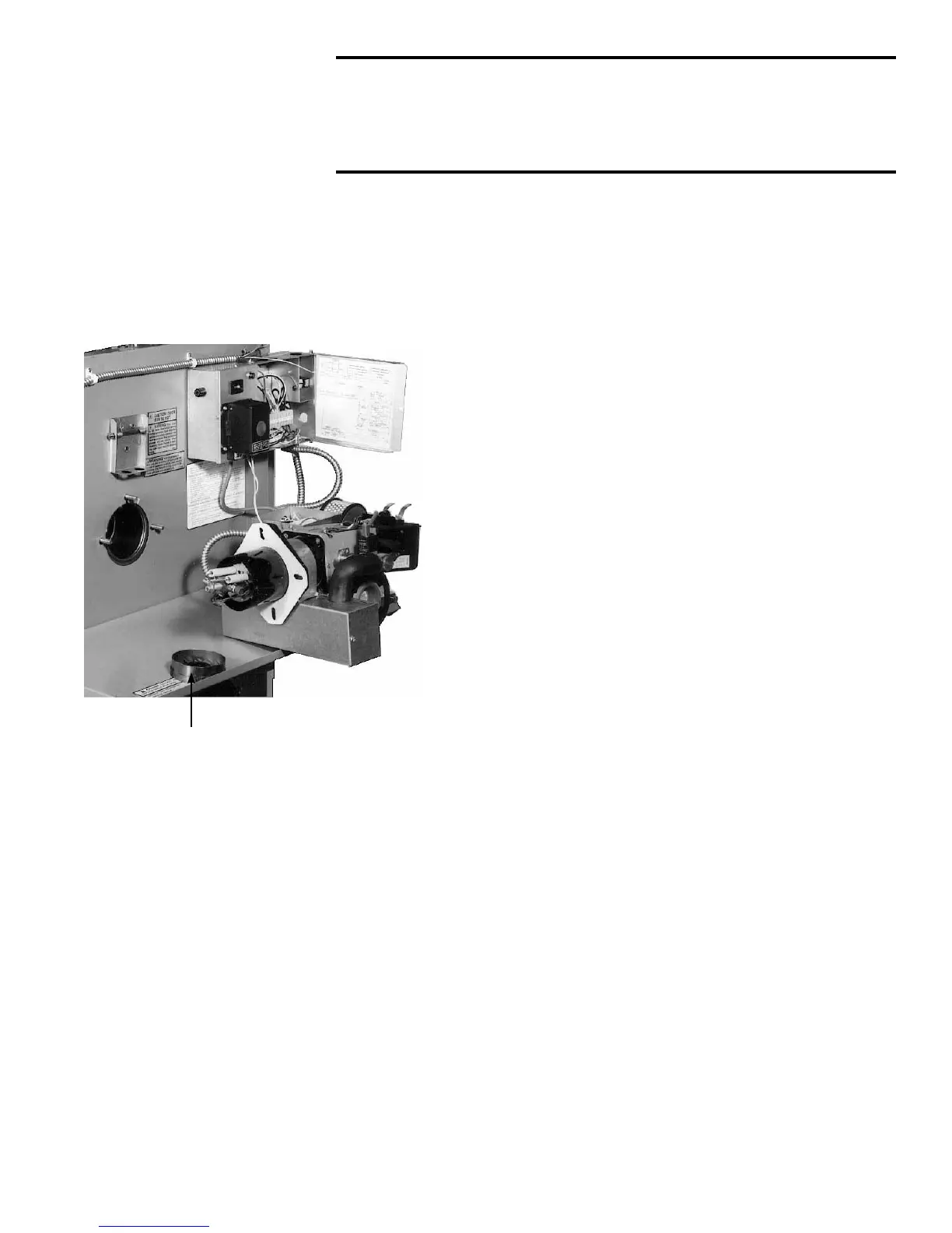
Removing Burner
and Cleaning End
Cone, Nozzle,
and Electrodes
End Cone
Removed
WARNING: Turn off the electric power before burner
is removed for service.
To gain access to the end cone, the burner must be
removed.
1. To Remove Burner
• Locate the two yellow wires that go from the burner to the ignition
controller.
• Disconnect these wires at the terminals on the ignition controller.
• Remove the three nuts and washers that retain the burner to the
heater.
• Slide the burner off the bolts and rotate as illustrated.
2. To Remove/Clean the End Cone
• Remove the screws that hold the end cone to the
burner tube.
• Remove and clean the end cone using a stiff wire
brush.
• Check the end cone for deterioration and replace if
deterioration exists.
3. To Remove the Nozzle (requires both a 1” and a 5/8”
open-end wrench)
• To prevent the fuel line assembly from twisting, use a
1” open-end wrench to hold the nozzle adapter while
removing the nozzle with a 5/8” open-end wrench.
• Clean nozzle by disassembling, washing thoroughly,
and blowing dry with compressed air.
• If nozzle face appears worn, replace the oil nozzle.
For Models RA/RAD350, use replacement oil nozzle
P/N 129382; for Models RA/RAD500, use replacement oil nozzle
P/N 157041. Annual nozzle replacement is recommended. This
nozzle is custom designed. Do not substitute nozzle.
• Replace the end cone.
NOTE: Be sure NOT to damage the “O” ring on the nozzle. If the
“O” ring appears damaged, replace the nozzle.
4. Inspect the Electrodes
• The electrode porcelain insulators must be free from carbon,
oil, dirt, pinhole leaks, cracks, moisture and evidence of over-
the-surface arc tracking. Otherwise, short circuiting could cause
ignition problems. If any of these conditions exist, replace with
new porcelain insulators (Replacement kit P/N 269820).
• If a need for service or replacement is determined, see
instructions on page 32.
5. Reassemble
• Check the gasket. If in tact, position it over the studs. If damaged,
replace with like replacement.
• Line the burner up with the studs and slide the tube into the
heater.
• Using the nuts and washers, attach the burner mounting ange.
• Re-connect the yellow wires to the ignition controller.