Form I-RA/D 350/500, P/N 131090R12, Page 33
Cleaning Oil
Pre-Heater
System
Maintenance
Procedures
Continued
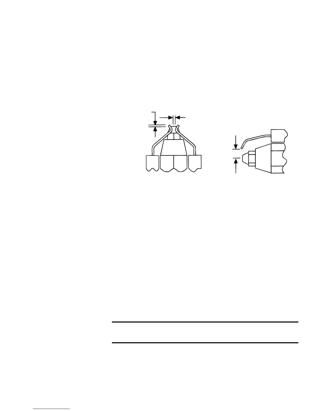
Electrode Adjustment
Check the placement of the electrodes according to the illustration below.
If adjustments are required, loosen the 1/4” screw. Make adjustments in
the order listed below. Recheck, and if necessary, re-adjust until elec-
trodes are in proper position.
1) From center of nozzle orice to electrode - up 5/16”
2) Electrode Gap (distance between electrodes - 1/8”
3) Relationship of the end of the electrodes to the tip of the
nozzle - 1/8” ahead
4) Relationship of the tip of the nozzle to the inside radius of
the end cone -- Flush to 1/16” ahead
- NEVER BEHIND
Reassembling
the Fuel Line
Assembly
1. To reassemble the Fuel Line Assembly
• Slide the fuel line assembly into the burner housing and the
burner tube.
2. Connect the fuel connection assembly to the fuel line assembly.
• Tighten the 5/16” inverted are nut rmly. Then tighten the
connection nut. Do not move the escutcheon plate.
• Check the spacing between the oil nozzle and the end cone.
Refer to Electrode Adjustment above.
3. Connect the eight wires in the fuel line assembly wiring bundle.
Refer to the wiring diagram in the Appendix of this manual or the
wiring diagram on the heater.
4. Push the air line hose out through the burner housing and
reconnect it to the air compressor.
5. Close the spark transformer cover and attach with the two screws.
Be certain transformer clips make contact with the electrodes.
NOTE: Once assembly is in place, verify that the nozzle, end cone, and
electrodes are correctly located.
WARNING: Turn off the electric power and allow the
pre-heater to cool before servicing.
1. Remove the Burner
• Locate the two yellow wires that go from the burner to the ignition
controller. Disconnect these wires at the terminals on the ignition
controller.
• Remove the three nuts and washers that retain the burner to the
heater. Slide the burner off the bolts and rotate.