23
SERVICE - 1
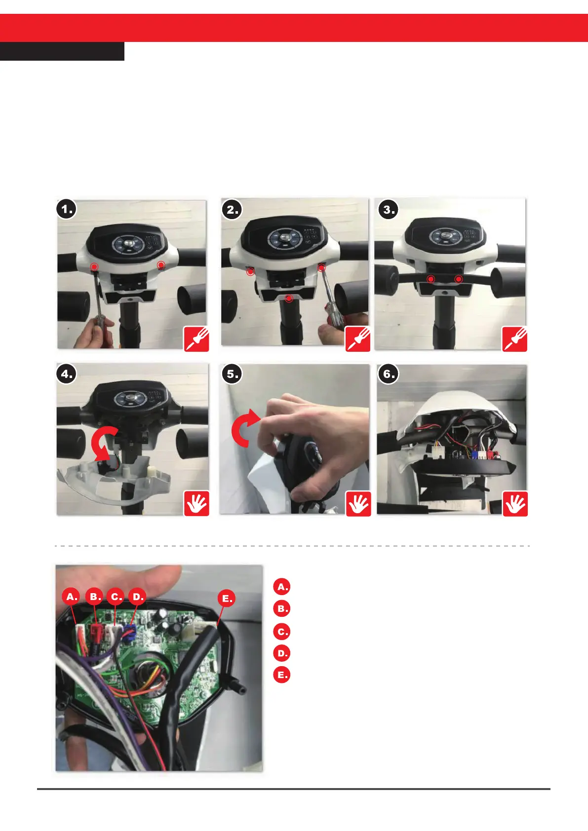
Steering Cover Repair
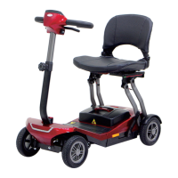
Board Circuit Comparison Diagram :
Metal power switch connector
Power connector
Starter VR connector
Buzzer connector
Main cable connector (including headlight,
taillight, and folding / unfolding board)
1.Remove the steering head rear cover and panel screws (12mm, 2pcs)
2.Remove the three screws (12mm, 3pcs) on the steering head rear cover
3.Remove the starter rod screws (8mm, 2pcs)
4.Detach the steering head rear cover
5.Detach the panel and steering head top cover
6.Make sure all the connectors on the board are properly fastened
※When reassembling be sure to use the exact reverse sequence of operations.