24
SERVICE - 1 - 1
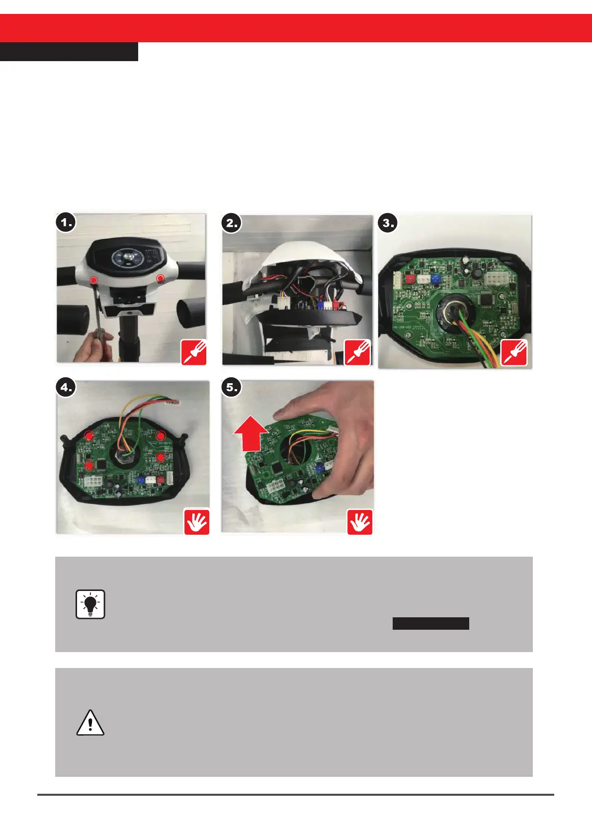
Top Control Panel Repair
•The top control board connectors are color-coded to prevent mistakes
when reconnecting. However, It is recommended that a photo be taken
that shows the connector locations before removing the board to prevent
a hassle during re-installation.
•Step 2. If it cannot be removed, please refer to SERVICE-1 Steering
Cover Repair for complete details on disassembly.
•Please do not touch the terminals on the top control board, to prevent
damage to the control board circuitry.
•During replacement of the top control board, do not disturb the metal
power switch in the center.
•Make sure to match the connector colors and do not make modifications
to any cables or connections. Do not force connectors to avoid damage
to the electrics and the scooter.
1.Remove the steering head rear cover and panel screws (12mm/2pcs)
2.Open the steering head top cover
3.Also remove all of the connectors on the top control board (refer to the instructions on
the previous page for connectors)
4.Remove the four screws (8mm/2pcs) on the top control board
5.Remove the entire top control board and replace with a new one
※After replacing the parts be sure to use the exact reverse sequence of operations for
reassembly.