10
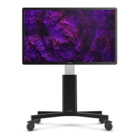
Riva
11
Share, inspire, have fun!
With CTOUCH by your side.
ctouch.eu
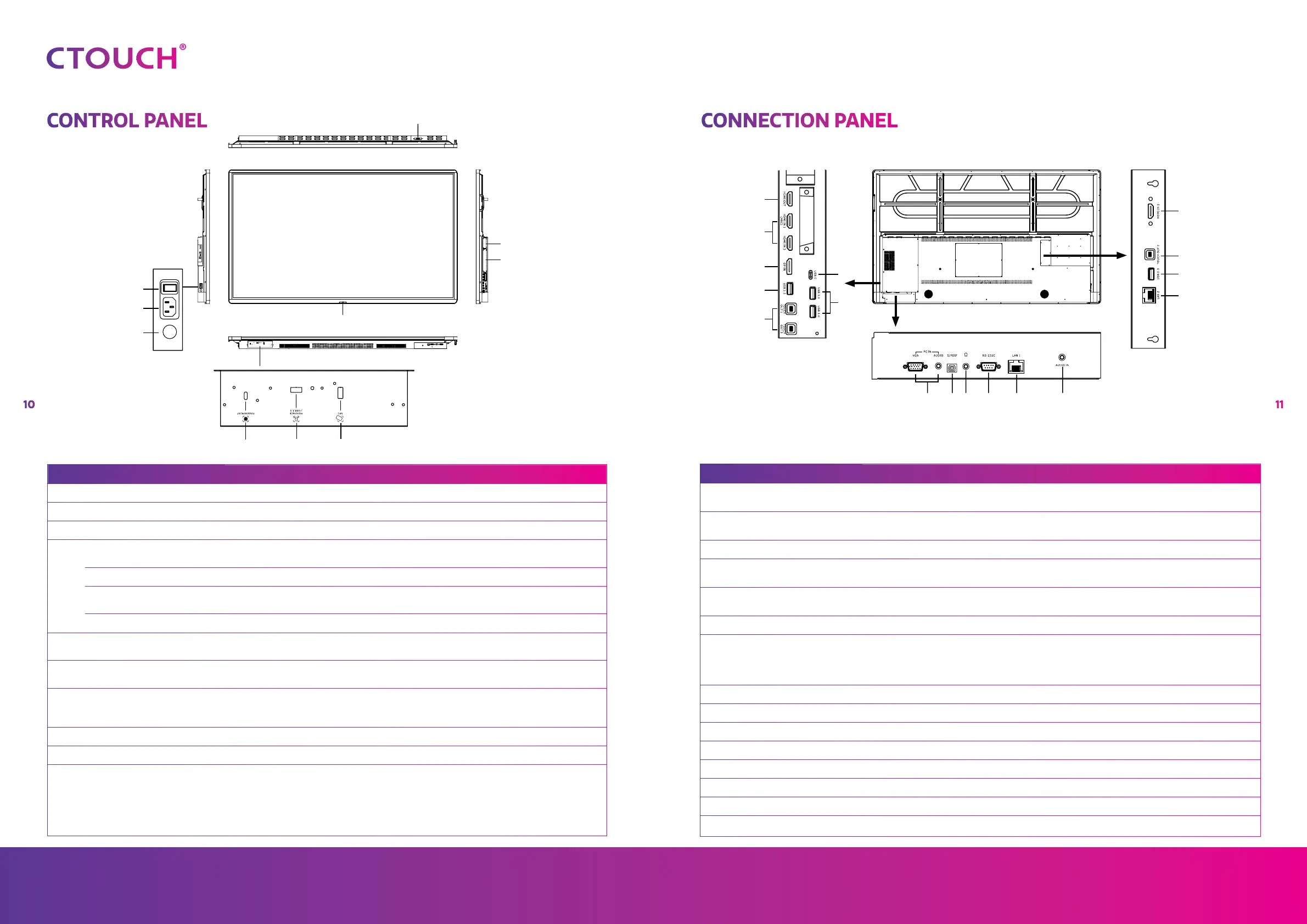
NR. DESCRIPTION
1 USB (3.0) (for camera) This port is designed for connecting a webcam.
2 CTOUCH module slot Insert an CTOUCH module (optional).
3 OPS module slot Insert an OPS module (optional).
4
CTOUCH Button
Power LED Red: In standby mode.
Blue: In power on mode.
Remote control sensor Aim the remote control towards this spot on the CTOUCH interactive display.
Power Press the button for about 2 seconds to turn the CTOUCH interactive display on or
off.
Navigation Bar control Press the button once to call up the Navigation Bar.
5 NFC reader port Insert the CTOUCH NFC reader (optional).
Note: this port is dedicated to the NFC reader, normal USB device will not work.
6 USB 2.0/Human Presence
Detection port
Insert the CTOUCH Human Presence Detection module (optional).
Note: this port will also work with USB devices.
7 Fingerprint scanner port Insert the CTOUCH fingerprint scanner (optional).
Note: this port is dedicated to the fingerprint scanner, normal USB device will not
work.
8 Fuse 12A 250V
9 AC IN Plug the AC cord into this jack and into a power outlet.
10 Power Switch Push (I) to turn on the power, push (O) to cut off the power.
Note: for safety reasons do not cover the power switch.
10
8
4
2
3
7 6
9
5
1
2
3
5
2
7
14
12
9 10 11
8
7
4
6
12 13
NR. DESCRIPTION
1 HDMI out Connect an external device with a HDMI cable to this port to output the image and sound
of the CTOUCH interactive display.
2 HDMI 1/2/3 in Connect an external device with a HDMI cable to this port.
Note: connect an external HDMI device which supports ARC to HDMI 1.
3 Display Port (DP) in Connect an external device with a DP cable to this port.
4 USB-C Connect an external device with an USB-C cable to this port.
Note: the display supports USB 3.1 Gen 2.
5 USB 2.0 Connect a USB device to this port for Android.
Note: use this USB-port for manual firmware updates.
6 USB 3.0 Connect a USB device to this port for OPS or Android.
7 Touch out 1/2/3 Connect an external device to support touch control of the external device on the display.
Note: Windows is Plug & Play, for Apple a driver is needed.
Note: Touch out 1 connects to HDMI 1, Touch out 2 connects to HDMI 2 & Touch out 3
connects to HDMI 3, DP & VGA.
8 VGA in Connect an external device with a VGA cable and Mini Jack to this port.
9 SPDIF out Connect a digital sound system to this SPDIF jack.
10 Headphones in Connect a headphone to this jack.
11 RS-232C Connect a DB-9 cable to this port for remote control, service and other uses.
12 LAN 1/2 Connect the external network or router with an LAN cable to this port.
13 Audio in Connect an external audio device with a Mini Jack cable to this jack.
14 USB 2.0 Connect a USB device to this port for OPS and Android.
Note: for all audio devices the selected source is audible.
CONTROL PANEL CONNECTION PANEL
1