2 Installation and Removal of Engine Parts
14
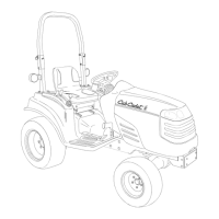
12. Disconnect the harness E from the following engine
parts.
From engine right side
• Water temperature sensor
• Solenoid valve for fuel cut
• Glow control system
• Fuel pump
• Oil pressure switch
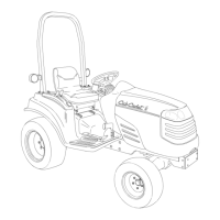
13. Remove the air intake hose.
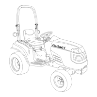
14. Disconnect the harness E from the following engine
parts.
From engine front side
• Fuse box
• Air heater relay
• Air heater control box
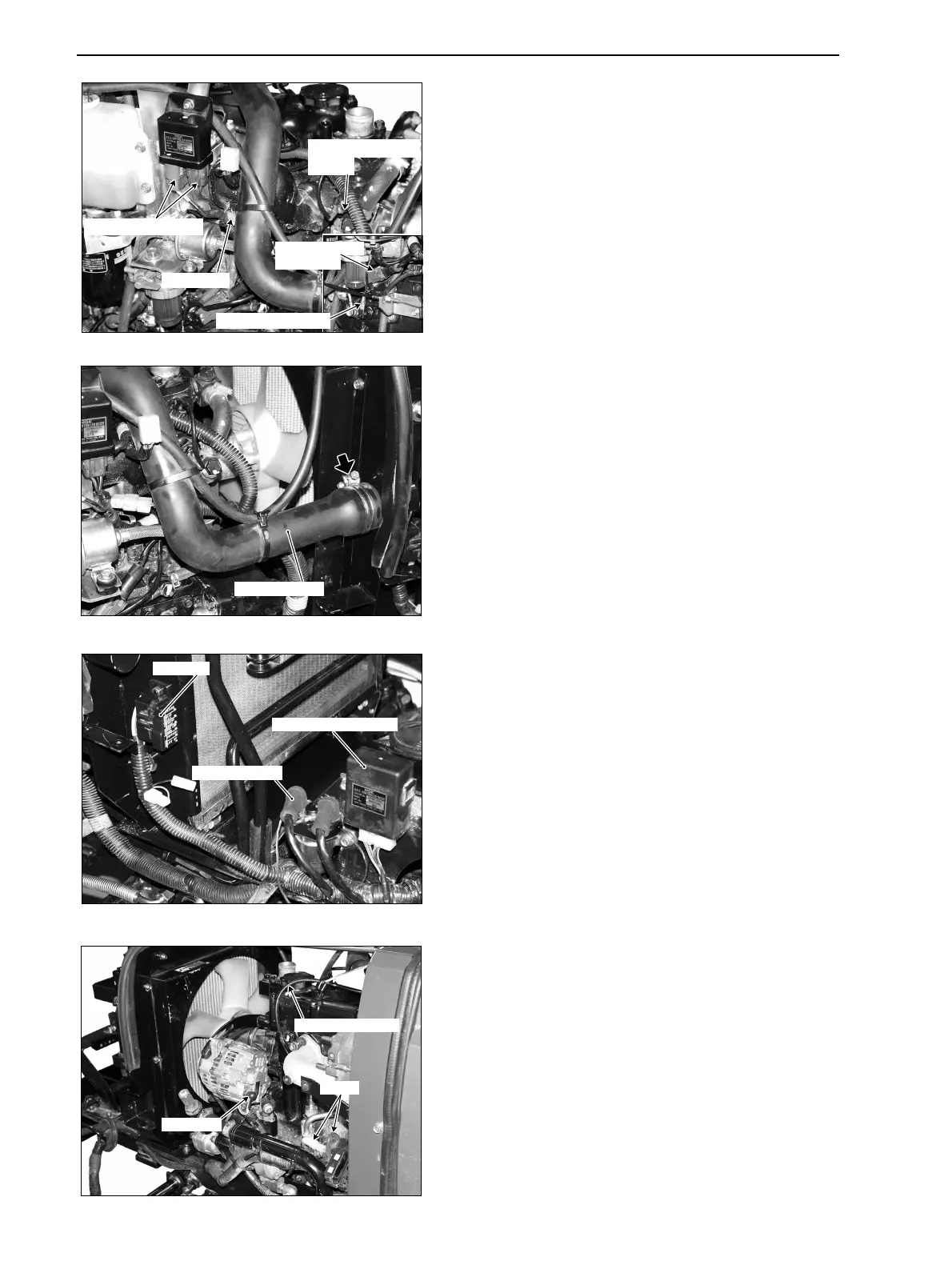
From engine left side
• Starter
• Alternator
• Tachometer cable
Watertemperature
sensor
Fuelpump
Oilpressureswitch
Solenoidvalve
forfuelcut
Glowcontrolsystem
GZ3W21-012
Airintakehose
GZ3W21-013
Airheatercontrolbox
Fusebox
Airheaterrelay
GZ3W21-014
Starter
Tachometercable
Alternator
GZ3W21-015
www.mymowerparts.com
K&T Saw Shop 606-678-9623 or 606-561-4983
 Loading...