25
01021076
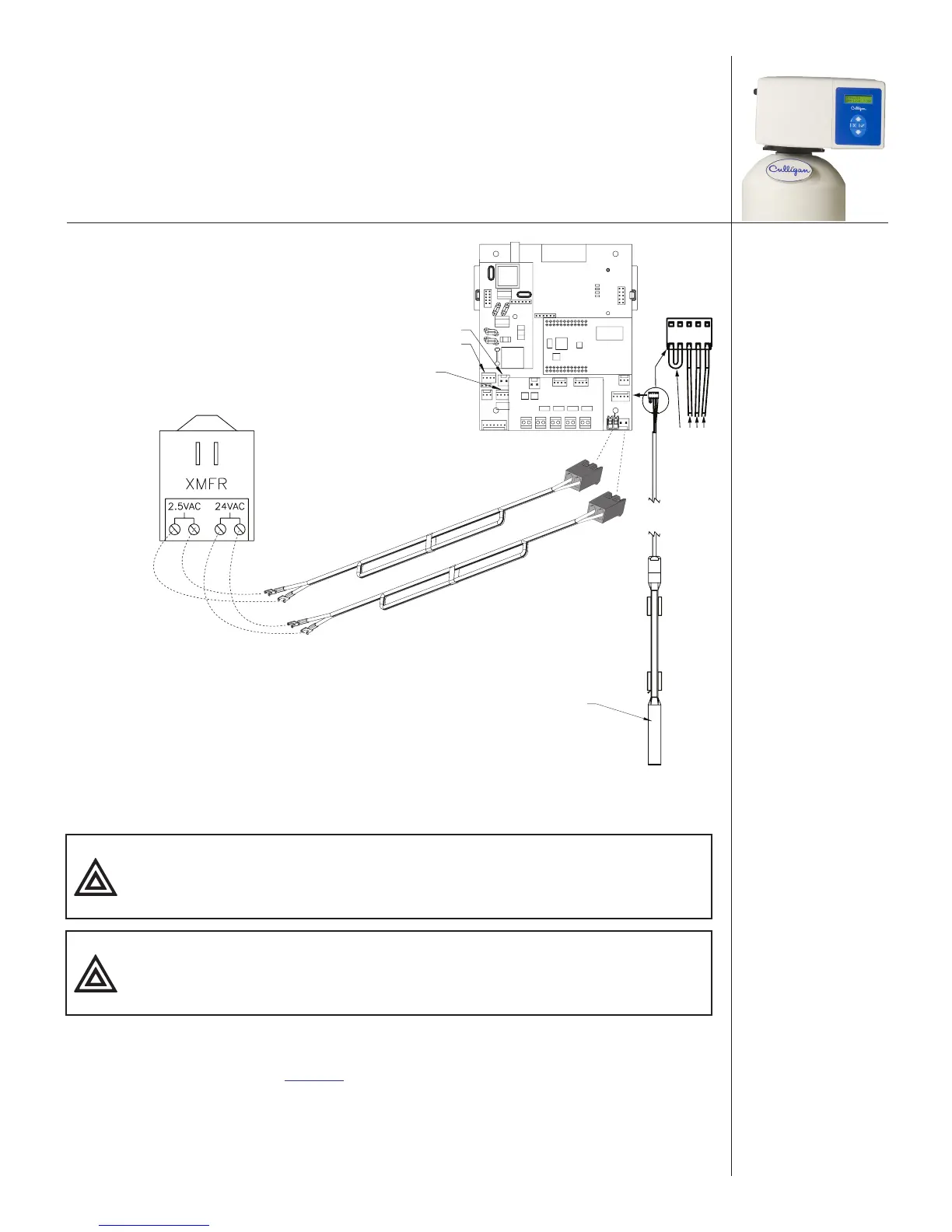
Power to circuit
board 24V
Red
Black
Blue
White
Connector Plugs
POSITION SENSOR CONNECTOR
MOTOR CONNECTOR
FLOW METER CONNECTOR
AQUA-SENSOR PROBE
PHONE
24v
2.5v
Power to circuit board
2.5VAC required only for
Aqua-Sensor installations
Power cable should be
plugged to 24V
connectors—right side
Aqua-Sensor power
cable should be
plugged to 2.5VAC
connectors—left side
Figure 20. 2.5 VAC Aqua-Sensor® power connection.
12. Connect the power supply cord to the circuit board.
CAUTION! Verify wiring from the terminals to circuit board are correct
before applying power to the control. 24 V power must not be
applied to the 2.5 VAC terminals.
CAUTION! Connecting 24 V to the 2.5 VAC connection on the circuit board
will damage the circuit board.
13. Reattach the electrical enclosure cover to the control valve.
a. Align the circuit board in the enclosure with the three support brackets on the control
valve frame. See Figure 21.
b. Push the enclosure onto the control valve, inserting the circuit board edge in the slots
on the control valve frame and the screw on the enclosure with the hole on the cover.