24 Culligan® CSM Series Softeners
24 Cat. No. 01016370
Tubing Installation
The tubing assembly is shipped in the same carton as the controller. The tubing is suppled in lengths pre-cut to connect
up to a 3” Brunermatic valve.
1. Using the tubing supplied, interconnect the controller, Brunermatic valve, brine line diaphragm valve (multiple
units), and any accessory kits ordered with the system. Refer to Figure 35, Figure 36, and Figure 38 for system
tubing diagrams.
2. For ease of installation, some tube fittings on the system are the push-in type. Tubing is simply inserted into the
fitting collet to make a secure, leak free connection. Refer to Figure 33 and Figure 34 for details on proper con-
nection and disconnection.
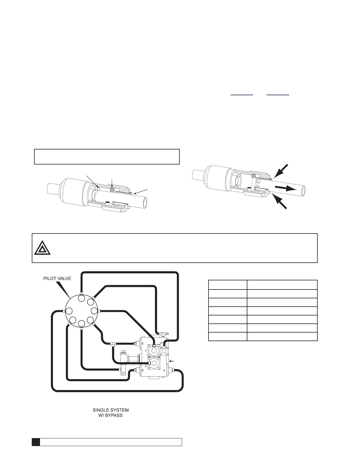
CONNECTION
To make a connection, simply push the tubing in by hand.
NOTE the fitting will grip before it seals. Make certain
the tubing is fully pushed into the tube stop.
TUBE STOP
O-RING
COLLET
Figure 33.
DISCONNECTION
To disconnect tubing, push in the collet against the face
of the fitting. With the collet held against the face of the
fitting, the tubing can be removed.
Figure 34.
CAUTION! The port numbers on the Brunermatic valve may not coincide with the ports
on the MVP pilot valve. Refer to the port numbering chart for cross-reference
information.
6
P
DR
1
3/4
2
5
Brunermatic
Valve
Figure 35.
Table 7. Cross Reference Port Chart
Pilot Valve Brunermatic Valve
1 1
3 2
2 4
4 5
5 6
6 17

 Loading...


