Installation 27
Cat. No. 01016370
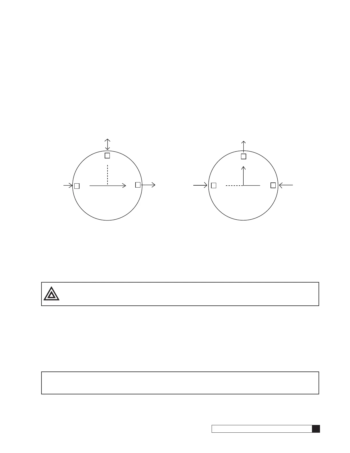
Sequence of Operation
When a softener is in standby or a regeneration cycle, the MVP controller sends a signal to the P7 SOL-VIV terminal of
the primary circuit board, activating the solenoid valve. The orange LED will be on at this time. When the solenoid valve
is electrically activated, ports #1 and #2 of the solenoid (Figure 39) become common. This will direct pressure from the
constant IN pressure supply to Brunermatic diaphragm valve #4, which prohibits the flow of water through the outlet of the
Brunermatic valve.
Once the controller signals the unit to return to a Service status, the signal from P7Solvlv is removed and the solenoid
valve is deactivated. When the solenoid valve is electrically deactivated, ports #1 and #3 of the solenoid become com-
mon. The orange LED will not be on at this time. This will vent pressure, from Brunermatic diaphragm valve to port #4 on
the pilot valve body and then to drain. Brunermatic valve #4 opens which allows softened water to flow through the outlet
of the Brunermatic valve.
2
3
1
N
O
/
To port #2 on Pilot Valve Body
(no pressure)
N
O
/
N
C
/
From
"IN"
on
Pilot Valve
Body
(pressurized)
From
Port #4
on
Brunermatic
Valve
(no pressure)
Solenoid Valve Not Energized
When Tank "Online"
3
2
1
N
O
/
N
O
/N
C
/
To port #2 on Pilot Valve Body
(pressurized during regen,
no pressure in standby mode)
To
Port #4
(pressurized)
From
"IN"
on
Pilot Valve
Body
(pressurized)
Solenoid Valve Energized
When Tank
in Regen or Standby
Solenoid Valve
Solenoid Valve
Figure 39.
Electrical Installation
CAUTION! Observe the precautions listed below before electrical installation of your MVP control-
ler. Failure to do so may cause permanent damage to the controller.
• Follow the local electrical code requirements.
• Be sure electrical power is off and disconnected at the source before completing any wiring/cabling connections.
• Provide a dedicated 120-volt circuit for the MVP system to ensure maximum electrical protection.
• DO NOT include the MVP wiring cables in any conduit or raceway containing other 120-volt or higher circuits.
• Maintain a distance of at least 10 feet between the MVP controller and any electrical distribution panels, raceways
carrying 300 volts or more, and electrical motors of 1 horsepower or more.
• Use the cabling provided. Failure to do so may effect performance of the MVP controller adversely.
NOTE One transformer is required for each controller in the system. Do not attempt to operate
multiple controllers without a dedicated transformer for each or your system will experience
operational difficulties.

 Loading...


