Installing Accessories 27
Cat. No. 01029343
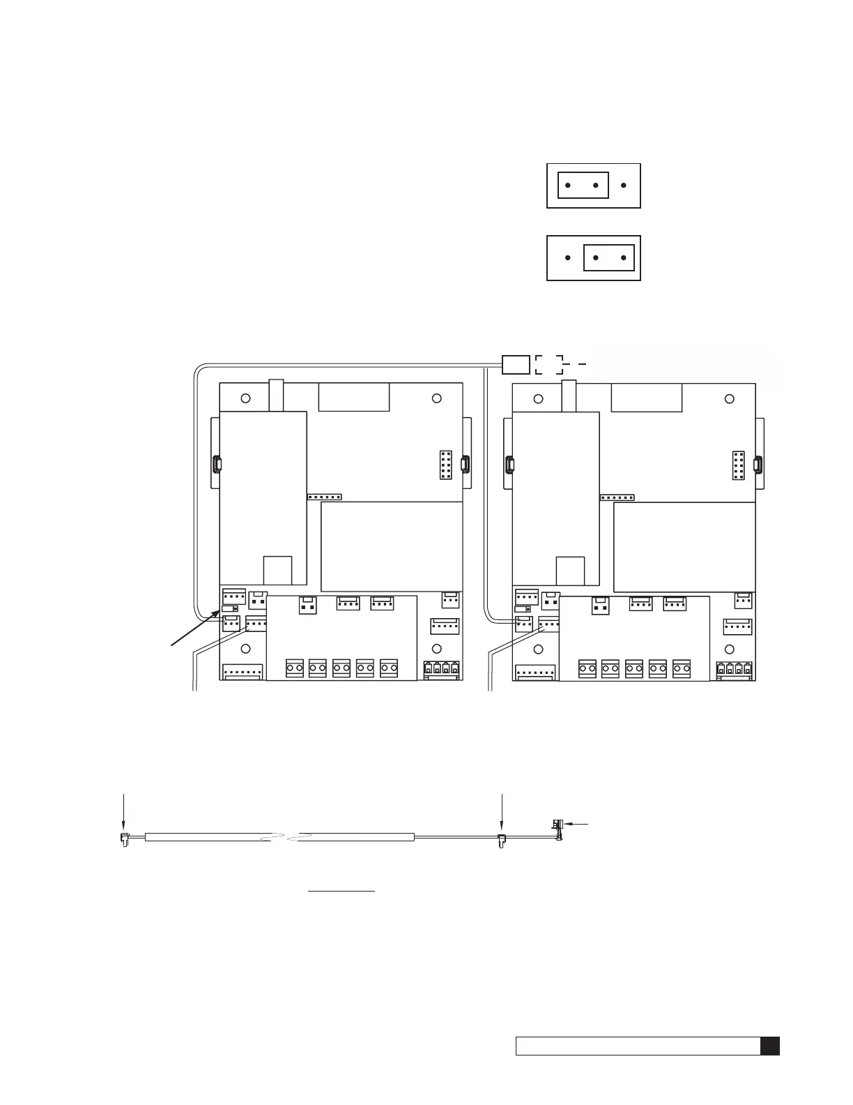
IMPORTANT—Setting the Jumpers for GBE to GBE RS485 Communication
For GBE controls to communicate via RS485 properly, the first and last
units must have the jumpers set to pins 1 and 2 on terminal J22 (see
Figure 29 at right). All middle units should have the jumpers on pins 2 and
3 (see Figure 29).
Progressive, Parallel or Alternating Flow
The diagram below (Figure 30) shows duplex connections. Repeat the
connections on any additional systems.
To Additional Units
(if necessary)
Communication Cable 01016327
Jumper
Location
Flow Meter Flow Meter
Unit 1 Unit 2
MODEM
BOARD
BASE BOARD
RF BOARD
AUXILARY BOARD
RJ11
PHONE
MODEM
BOARD
BASE BOARD
RF BOARD
AUXILARY BOARD
RJ11
PHONE
Figure 30. Duplex connections.
To RS 485 Comm Port
on GBE Circuit Board, #1
CABLE 01016327
To RS 485 Comm Port
on GBE Circuit Board, #2
PARALLEL
Additional communication cable
connections are used when there
are three or more controls. Connect
end of second-(01016327) cable
to this connector and other end of
cable to RS 485 Comm Port on third
GBE Circuit Board.
Figure 31. Parallel cable for Smart Controller.
Jumper location for
first and last units
(end units).
Jumper location for
middle units.
1 2 3
Figure 29.