Installing Accessories 35
Cat. No. 01029343
Installing the Landline Modem In the Remote
Open the remote monitor housing by removing the two screws and squeezing the sides of the monitor housing slightly.
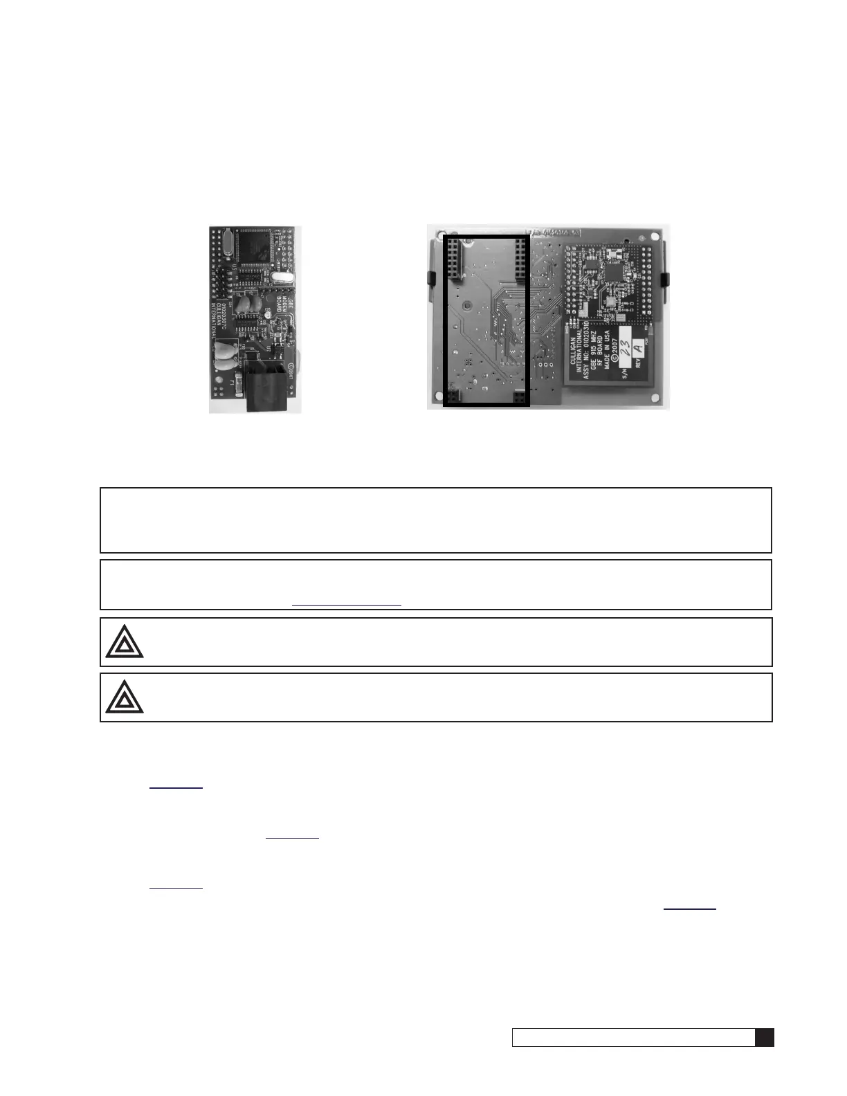
Insert the modem board (P/N 01020747) into the socket on the back of the remote board (see Figure 44). Make sure that
all of the pins in all four connectors are aligned and make sure the modem is fully seated into all of the sockets. Snap the
two halves of the remote housing back together using light finger pressure and insert the two screws.
Figure 44. Back of remote board.
Installing the Cell Modem (P/N 01026799)
NOTICE In addition to the sockets, that are also used by a landline modem, the cell modem will also use
the Auxiliary Output 5’s sockets and the Data Port PLC Output’s sockets. Therefore Auxiliary Out-
put 5 can no longer be used for anything else, such as an alarm, and the Data Port PLC Output’s
sockets can no longer be used for anything else, such a connection to a Modbus Converter.
NOTE Use of the cell modem kit requires a one-year subscription to a Level 2 Telecom package. Self-service
registration is available at www.cport.culligan.com under the Technical Service tab on the Telemetry
page’s subpage called Setup Self-Service.
CAUTION! Avoid contact with any pins to minimize any static damage.
CAUTION! Always hold cell modem and circuit board by the edges to avoid damaging the boards.
1. Carefully remove the Cell Modem Kit and SIM card from packaging.
2. The assembly has three circuit boards connected together in a stack. On the bottom of the stack is the largest
of the three circuit boards; it is also green. Verify that the protruding pins are not severly bent or damaged. See
Figure 45.
3. On top of the stack is the Arduino board. This board must be removed to gain access to the SIM card slot on
the center of the board. Separate it from the stack by holding the board in the center by the edges, and gently
pull them apart. See Figure 46
4. Slide the cover in the direction marked “open” until it unlocks and flip it open. The SIM card slot is exposed on
the center of the circuit board. The slot has markings on it to indicate which direction to open and lock it. See
Figure 47.
5. Locate the SIM card from the package and slide it into the grooves of the cover as shown in Figure 48.
6. Flip the cover closed by sliding it in the “open” direction and make sure it is seated properly in the slot.