36 Culligan® Culligan Top Mount (CTM) Water Filters
36 Cat. No. 01029343
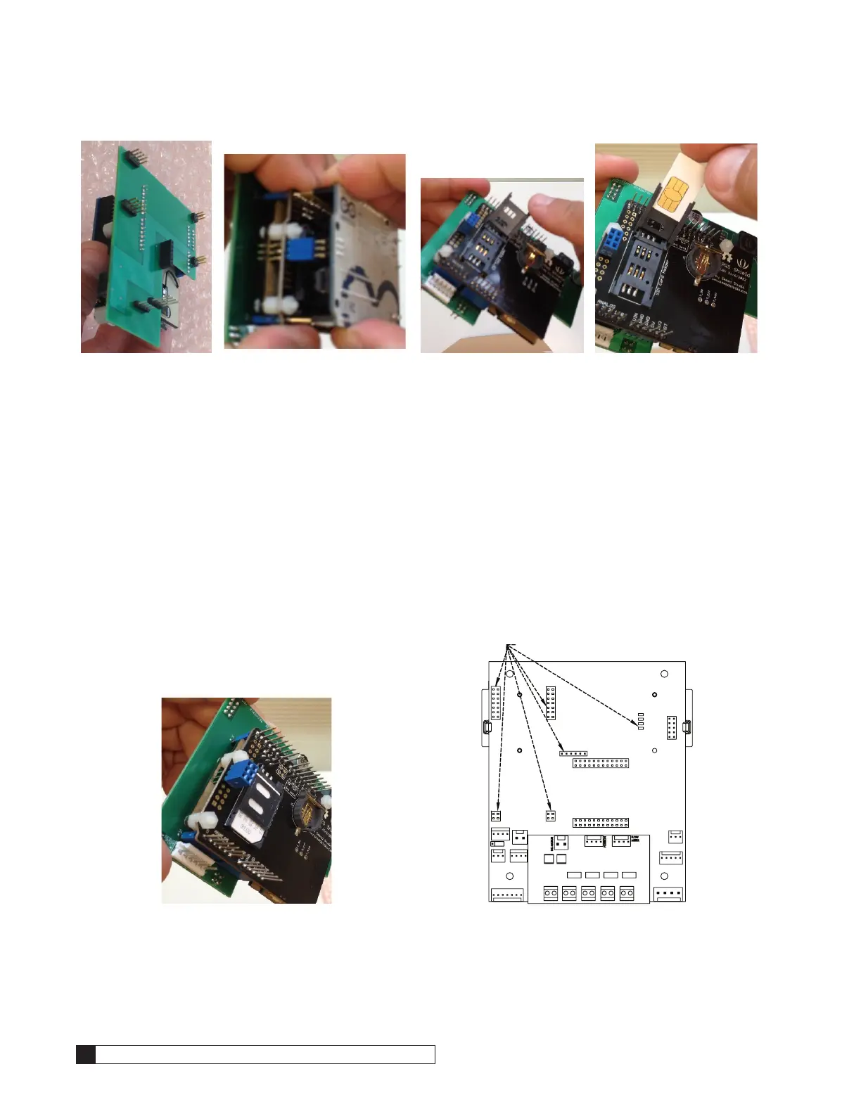
Figure 45. Figure 46. Figure 47. Figure 48.
7. Once the SIM card is seated flush, slide the cover into the “lock” direction and secure it with a click. Verify that it
can not flip open. See Figure 49
8. Reassemble the Arduino board on top of the stack by aligning the pins as shown. Verify that there are no mis-
aligned pins. Apply slow, even pressure and press the boards together until fully seated.
9. Remove the GBE control board from its enclosure and expose the back, verifying that there are no obstructions
in the sockets where the modem or alarm relay boards are typically located. See Figure 50.
10. Align the pins on the cell modem stack so that all of the connections are made at the same time. The four long
pins should line up onto the right side of the GBE and the rest of the pins onto the left. Get the long pins started
first into the four holes where the alarm relay typically connects to then start the remaining pins into the sockets
where the analog modem typically connects to. At the same time, make sure that the debug port pins find the
socket on the cell modem. Once all the connections are started, apply slow even pressure and seat all the con-
nections. See Figure 50.
11. Reinstall the GBE into the enclosure and make the rest of the connections as usual. Verify that there is no
physical interference that could dislodge the cell modem stack.
12. Power up the system and verify normal operation
Figure 49.
J7
J10
J5 J6
J16
J17
Figure 50.