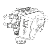
18 Culligan® High Efficiency 1.5 Water Filter
18 Cat. No. 01024514
Drain Line Connection
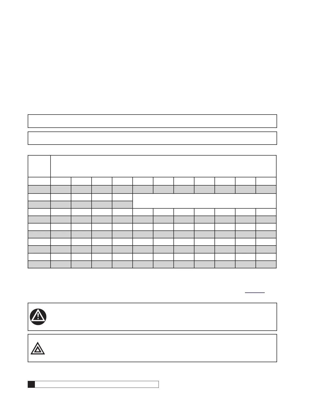
Refer to Table 3 for drain line length and height limitations under the applicable tank size.
1. Remove 3/4" pipe clamp from the small parts pack included with the control.
2. Route a length of 3/4" drain line from the drain elbow to the drain.
3. Fasten the drain line to the elbow with the clamp.
4. Secure the drain line to prevent its movement during regeneration. When discharging into a sink, or open floor
drain, a loop in the end of the tube will keep it filled with water and will reduce splashing at the beginning of
each regeneration.
NOTE Waste connections or drain outlets shall be designed and constructed to provide for connection to the
sanitary waste system through an air gap of two pipe diameters or 1 inch, whichever is larger.
NOTE Note: Observe all plumbing codes. Most codes require an anti-siphon device or air gap at the dis-
charge point. The system and installation must comply with state and local laws and regulations.
Table 3. Maximum drain tubing run length.
Ave.
Water
Press.
Height of Drain Tubing Discharge Above Floor Upon Which Filter Sets
psi 4 in. 1 ft. 2 ft. 3 ft. 4 ft. 5 ft. 6 ft. 7 ft. 8 ft. 9 ft. 10 ft.
kPa 0.1 m 0.3 m 0.6 m 0.9 m 1.2 m 1.5 m 1.8 m 2.1 m 2.4 m 2.7 m 3.1 m
30 44 ft 38 28 18
210 13.4 m 11.6 8.5 5.5
50 103 ft 97 87 77 67 57 47 37 27 17 7
350 13.4 m 29.6 26.5 23.5 20.4 17.4 14.3 11.3 8.2 5.2 2.1
70 129 ft 123 113 103 93 83 73 63 53 43 33
480 39.3 m 37.5 34.5 31.4 28.4 25.3 22.3 19.2 16.2 13.1 10.1
90 145 ft 139 129 119 109 99 89 79 69 59 49
620 44.2 m 42.4 39.3 36.3 33.2 30.2 27.1 24.1 21.0 18.0 14.9
120 153 ft 147 137 127 117 107 97 87 77 67 57
830 46.7 m 44.8 41.8 38.7 35.7 32.6 29.6 26.5 23.5 20.4 17.4
Circuit Board Connections
The 24 Volt power supply and flow meter wire harness is already connected to the circuit board. If no other circuit board
connections are required proceed to the First Time Setup. Refer to the instructions below and Figure 19 to Figure 26 for
connecting accessories to the circuit board.
WARNING! Disconnect all electrical power to the unit before connecting.
CAUTION! Grip all connections to the circuit board by the connecting terminals for assembly and
disassembly. Failure to do so could result in damage to the wire leads or connecting
terminals.