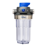
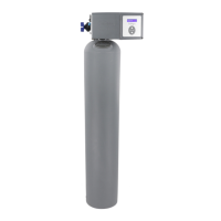
52 Culligan® High Efficiency 1.5 Water Filter
52 Cat. No. 01024514
Problem/Symptom Cause Solution
5. Loss of mineral to
drain
Improper drain line flow control Ensure that the control has the proper drain line
flow control.
Air in water system Ensure that system has proper air eliminator
control.
6. Mineral to service Defective outlet manifold Replace outlet manifold
7. Continuous flow to
drain.
Damaged O-ring. Replace O-ring.
Piston jammed in position. Replace piston or gear box.
Power failure while unit was in
regeneration.
Restore power to unit. Verify that unit is connected
to a constant power source.
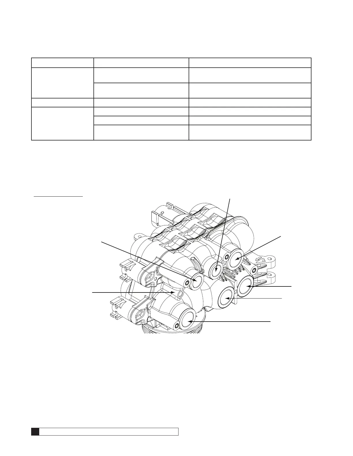
Flow Diagrams
Flow Valve Piston Locations
The flow valve controls the movement of untreated and treated product during regeneration cycles. Figure 60 identifies
each piston as installed. In this cycle (service), the P1 and P2/P3 valves are open; the P4, P5, P6, and PR valves and the
Brine Piston are closed.
BRINE PISTON
P6
P1
P4
PR
P5
P2/P3
PISTONS
P1–Inlet Piston
P2/P3–Outlet Piston
P4–Backwash Piston
P5–Rinse Piston
P6–Bypass Piston
Brine–Brine Piston
PR–Refill Piston
Figure 60. HE 1.5 valve piston locations.
Regeneration Cycle Sequence
1. Service
2. Backwash
3. Fast Rinse
4. Refill