DKC600 (U) & DKC600 (U)Y SLIDING GATE OPERATOR USER’S MANUAL
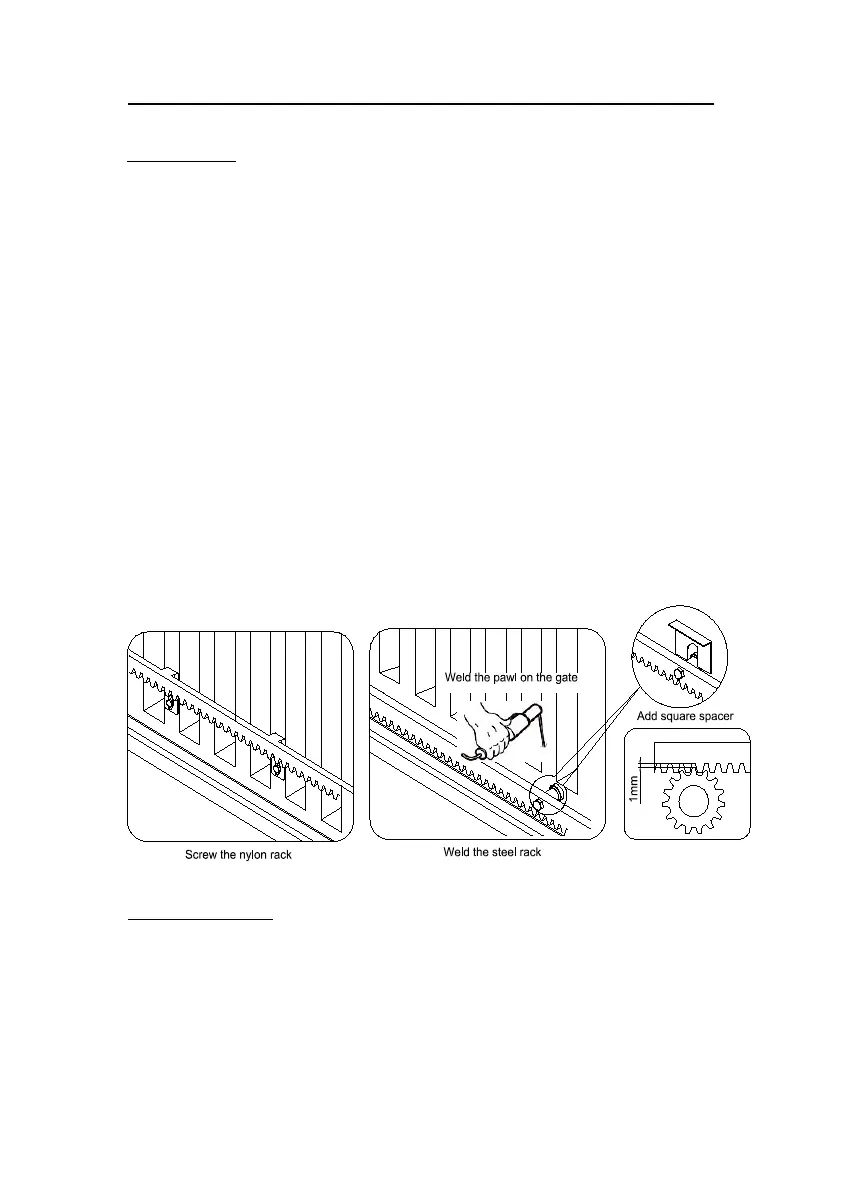
Installing the rack (see Fig.6)
Weld the steel rack
Manually move the gate to its closing position.
Place the three threaded pawls (in the same package with rack) on the rack element.
Lay the first piece of rack on the gear and weld the first threaded pawl on the gate.
Move the gate manually, checking if the rack is resting on the gear, and weld the second
and third pawls.
The space between rack and gear is about 1mm.
Bring another rack element near to the previous one. Move the gate manually and weld
the three pawls as the first rack, thus proceeding until the gate is fully covered.
When the rack has been installed, to ensure it meshes correctly with the gear.
If necessary, assemble the spacer between the rack and pawl to synchronise the teeth of
the two rack elements and keep racks in a straight line. See Fig.6
Screw the nylon rack
Manually move the gate to its closing position.
Lay the first piece of rack on the gear and mark the drilling point on the gate, drill a hole
and screw the bolt.
Move the gate manually, checking if the rack is resting on the gear, and repeat the above
operations.
Bring another rack element near to the previous one. Move the gate manually and carry
out the securing operations, thus proceeding until the gate is fully covered.
Fig.6
Magnets for limit switch
Install the magnet as shown in Fig.7 and Fig.8. The magnet and limit switch are used to control
the position of the gate. When the magnet is installed, release the gear clutch and push the
sliding gate manually to pre-determine the position. Weld or fit the magnet bracket to the rack
and then tighten the gear clutch. The lower bracket is for open position and higher bracket is
for close position. Finally adjust the magnet to the proper position by moving the gate with the
motor. The magnet should be 10-15mm away from the magnetic limit switch. If it is too far