DKC600 (U) & DKC600 (U)Y SLIDING GATE OPERATOR USER’S MANUAL
away, the switch will fail to work. Adjust the position of the magnets until the positions of the
opening and closing meet the requirement.
Important Note: Please note the two magnet brackets (fixed plate) are different: one is
higher and another is lower. Verify and if necessary exchange the two brackets position.
Also if necessary exchange the limit switch wires CL (close) and OP (open). Another
common problem is there are two reed switches inside the magnetic limit switch: one is
upper and another is lower. The magnet position can be installed in the middle so it
inducts both reed switches. Solution: adjust the magnet upper or lower.
Fig.7
It can be adjusted
Weld
Higher bracket
Magnet
Rack
Lower bracket
Magnet
Higher bracket
It can be adjusted
Style I: Weld the bracket on steel rack
Style II: Fit the bracket on steel rack or nylon rack
Lower bracket
Rack
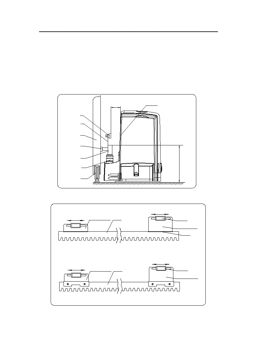
Fig.8
10-15mm
Magnet
Gate
Pawl
Rack
Gear
Guide rail
Magnetic limit
switch inside
19 teeth: 122mm
24 teeth: 132mm
Magnet
bracket