NOTE: Refer to chart L below and ensure desired height (H) is greater than the minimum
height for the size and type of conduit being bent.
24
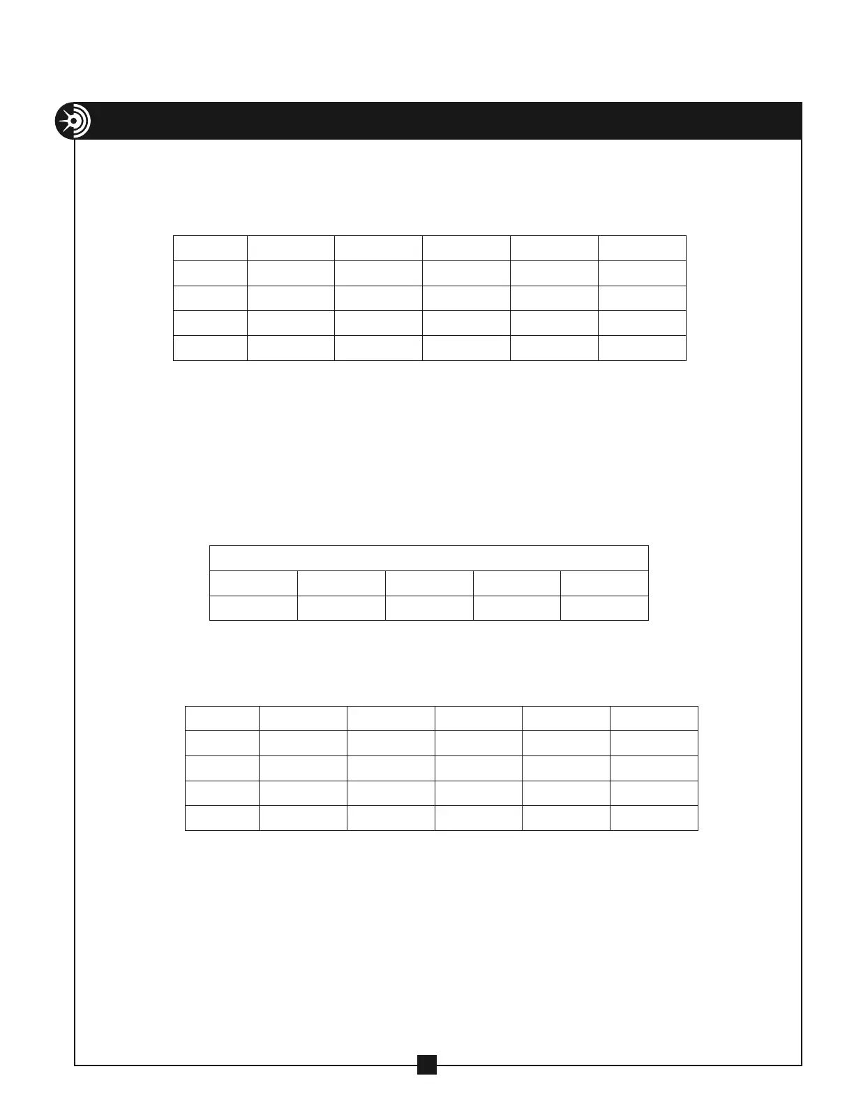
Chart M – “A” Values for Approximating Distances Between Marks for Offsets
ANGLE
15° 30° 45° 60° 90°
3.86 2.00 1.41 1.15 1.00
Chart L – Minimum Offset Height
ANGLE 15° 30° 45° 60° 90°
2 1/2"
2 9/16 6 13/16 12 1/2 19 1/4 33 15/16
3"
2 11/16 7 7/16 13 7/8 21 11/16 38 15/16
3 1/2"
3 1/8 8 5/8 16 3/16 25 1/4 45 3/8
4"
3 3/4 10 1/8 18 13/16 29 1/16 51 3/4
CALCULATING “C” VALUES FOR OFFSETS PAST AN OBSTACLE
To determine “C” value for laying out bending marks for offset heights other than those
listed, use the following formula:
C = A×H-B
“A” is a multiplier corresponding to the angle of bend and can be found in chart M. “B” is a
deduct value and can be found in chart N for the size of conduit and angle of bend.
Chart N – “B” Values for Approximating Distances Between Marks for Offsets
ANGLE 15° 30° 45° 60° 90°
2 1/2"
0.02 0.17 0.60 1.49 5.97
3"
0.02 0.20 0.71 1.77 7.07
3 1/2"
0.03 0.24 0.83 2.06 8.23
4"
0.03 0.26 0.93 2.31 9.23