COMMON BENDS LAYOUT INFORMATION
STUBS
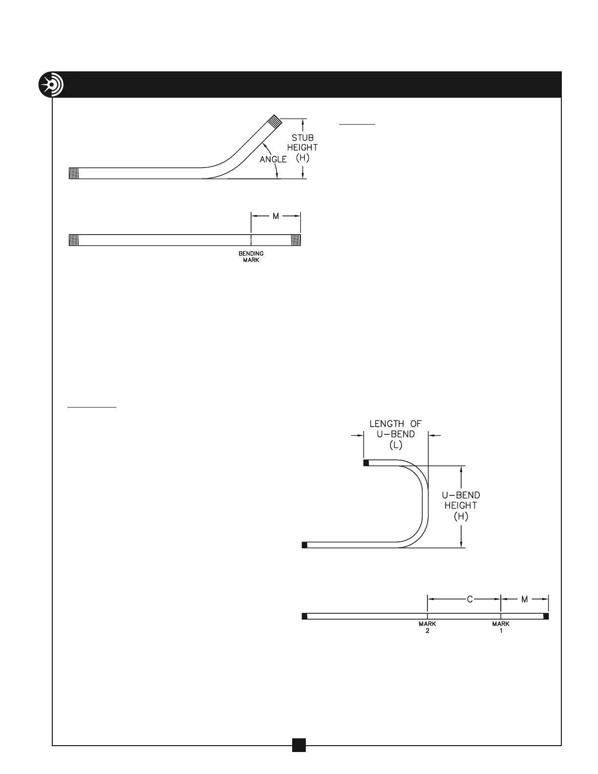
1. Determine the desired stub
height (H) and angle for the bend
(See figure 17A).
2. Locate the chart (see pgs. 20 - 23)
that corresponds to the size and
type conduit you are going to
bend.
3. Using the desired angle, locate
the “M” value that corresponds
to the desired height of bend.
4. Make a mark the distance “M”
from the end of the conduit. This
is your Bending Mark.
5. You may now proceed with the
bend.
17
U-BENDS
1. Determine the desired height (H) and
length (L) for the U-bend (See figure
17B).
2. Locate the chart (see pgs. 20 - 23)
that corresponds to the size and type
conduit you are going to bend.
3. Under the row corresponding to 90°,
locate the “M” value corresponding to
the length (L) of the U-bend.
NOTE: For a U-bend, the “L” value is
labeled “HEIGHT” in the charts
4. Make a mark the distance “M” from
the end of the conduit. This is your first
bending mark (Mark 1).
5. Under the row corresponding to 90°
locate the “C” value corresponding to
the height (H) of the U-bend.
6. Make a mark the distance “C” from
Mark 1. This is your second bending
mark (Mark 2).
7. You may now proceed with the bend.
FIGURE 17A
FIGURE 17B