Line Voltage
Wires
RED Switched Load
120-277VAC
BLACK Hot 120-277VAC
GRAY Analog Ground
VIOLET 0-10V Analog Output (dimming control)
Dimming Ballast
or LED Driver
(0-10VDC)
Hot
Neutral
GRAY (-)
VIOLET (+)
Dimming Ballast
or LED Driver
(0-10VDC)
Hot
Neutral
GRAY (-)
VIOLET (+)
RED 24VDC Power
BLUE Digital Input 1
Momentary
Contact
Switch
+24VDC
ON
OFF
YELLOW Digital Input 2
Low Voltage
Wires
Cap unused
wires.
*
*
*
0-10V Dimming output
5 mA available
Up to 10 LED drivers or fluorescent ballasts typical; the chance of low voltage errors increases with more.
Wireless Adapter with Power Monitoring
Model: WA100-PM
Input: 120-277VAC, 50/60 Hz
Load: 15A@120-277VAC Ballast or Incandescent, 1hp@120-230VAC
Output: +24VDC; 75mA
Ambient Temperature -4° to 149°F (-20° to 65°C)
FOR INDOOR USE ONLY UL 2043 Plenum Rated
Patent: www.daintree.net/company/patents
C
US
IEEE Address: 00228103007-00000
Load
White
Blue (Digital In 1)
Yellow (Digital In 2)
Orange (0-10V In)
Red (24VDC Output)
Black (Ground)
Green (Digital Out LSD)
Violet (0-10V Out)
Gray (Ground)
Relay
15A
15A+45mA
45mA
CONTAINS FCC ID: Z6G-DT357
CONTAINS IC: 10478A-DT357
CAN ICES-3 (B)/NMB-3(B)
RoHS
OFF
ON
DIP Switch Positions:
Wired
Switch Type:
Dimming
1 2 3 4 5 6
↓
O
N
Light output:
driver same as
switch
(#1,5 ON)
DIP Switches
Wireless Adapter (WA100-PM)
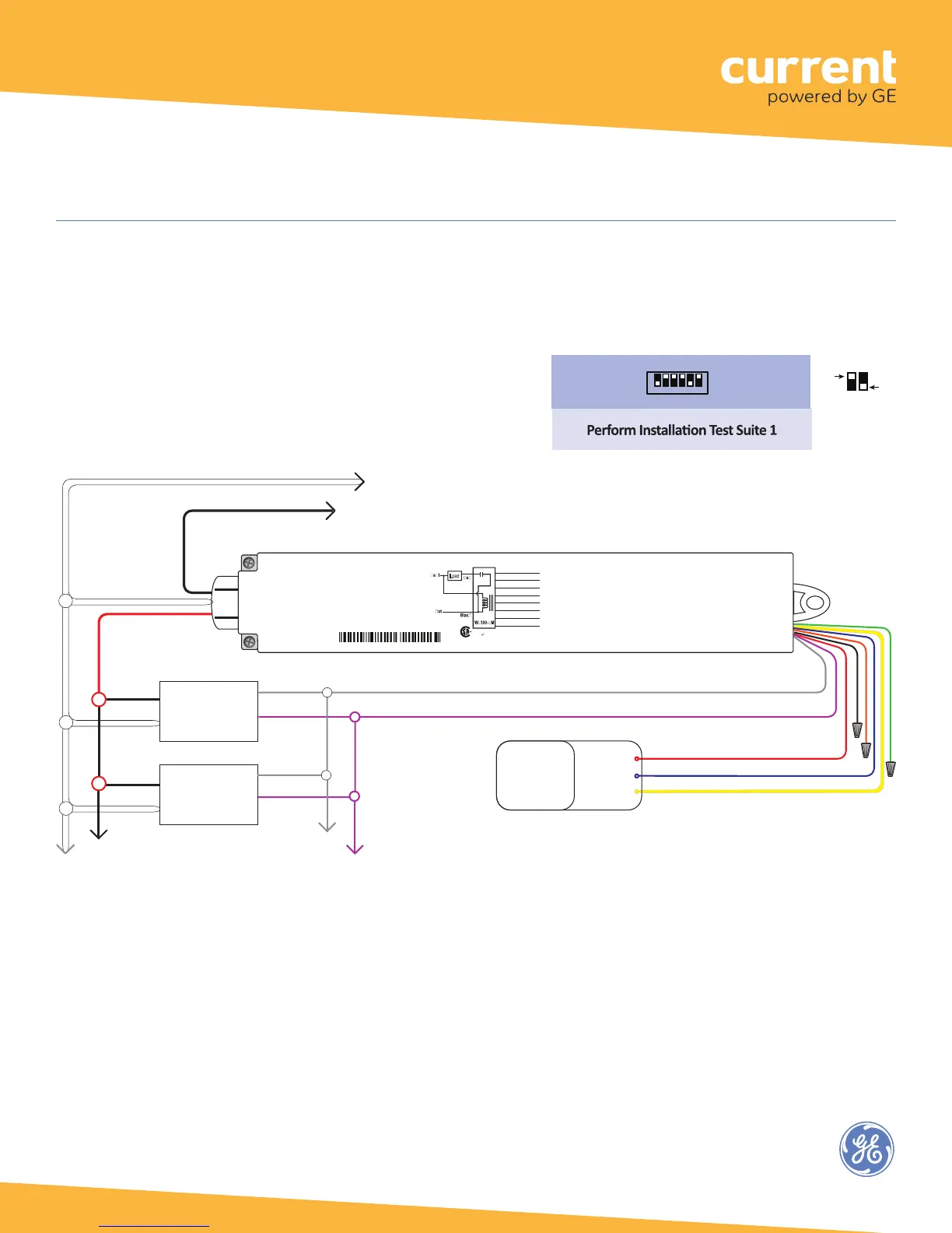
This configuration allows the WA100-PM to provide 0-10V dimming control and to switch light fixtures On/Off. It also
provides manual On/Off control through a low voltage momentary contact switch.
Fig. 10: Dimming Light Fixture(s) and Switch configuration:
12