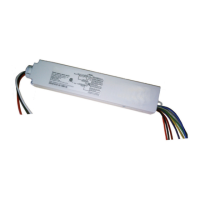
Wireless Adapter (WA100-PM)
Mounting
The WA100-PM is designed so that it can be mounted in
a variety of ways. Depending on the construction of the
fixture and its ability to propagate radio signals, it can be
mounted inside the fixture in the ballast/driver channel.
A printed bar code label with the full IEEE address is
included with the WA100-PM. Affix this label to the outside
of the fixture. Choose a standard location so that when
someone looks for fixtures containing a WA100-PM,
they will easily find it.
Using the Mounting Bracket
The mounting bracket included with the WA100-PM
and shown in the illustration below provides a screw-
mounting alternative. The bracket has a slot that
allows wires to remain connected as you snap the
bracket onto the WA100-PM nipple. The WA100-PM
can be secured at the other end using the integral
screw tab.
Alternatively, it can be mounted externally to a
junction box, enclosure, or fixture housing through
a 1/2” knockout.
Fig. 19: Mounting in driver channel
Fig. 20: Mounting with the included bracket
Fig. 21: Mounting external to the top of a suspended fixture
9.53”
(242 mm)
10.08”
(256 mm)
1.02”
(26 mm)
26
1.65”
(42 mm)
1.18”
(30 mm)
CONTAINS FCC ID: S4GEM35XA
CONTAINS IC ID: 8735A-EM35XA
Wireless Adap
te
r, Model: W
A100
Input: 120/230/277VAC, 50/60 Hz, 12A
12A Ballast or Incandescent Load
Output: 24VDC @75m
A
FOR INDOOR USE ONLY
Air Temperature -4 to 122°F (-20° to 50° C)
IEEE Address: 002281021002000A
Load
Black
Hot
Neut
Red
Whit
e
Blue (Digital In 1)
Yellow (Digital In 2)
Orange
(A
nalog In
)
Red (24VDC Output)
Black (Gnd
)
Green (Dig Out LSD)
Violet (0-10V Out)
Grey (Gnd)
C
Relay
WA100
UL 2043 Plenum Rated
12A
12A+45mA
45mA
12A
.
C
US
Occupancy
Sensor
WA100-PM
Light Fixture
Low Voltage
Wiring
(in sleeve)
1/2” Knockout in
Fixture Housing (top)
21