OFF
ON
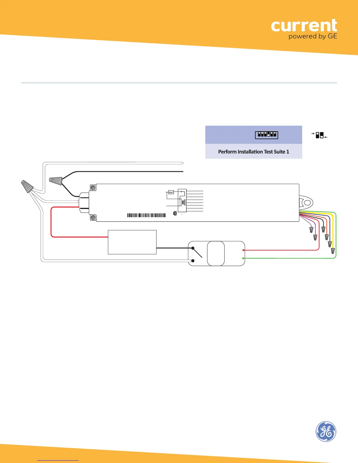
DIP Switch Positions:
Driver type:
On/Off (no dimming)
1 2 3 4 5 6
↓
O
N
Wired
Sensor:
None
* Line Voltage Wires and connections must be secured in an appropriate enclosure,
in accordance with all local, state, and national electrical codes and requirements.
Wiring connectors are not supplied. UL recognized wiring connectors must be used in the installation.
WHITE PHASE A (120V)*
RED Switched Line Voltage*
BLACK PHASE B (120V)*
PHASE A*
RED 24VDC Power
Aux.
Relay
+24VDC
GND
GREEN Digital Ouptut LSD
Lighting Load
Low Voltage
Wires
Cap unused
wires.
Wireless Adapter with Power Monitoring
Model: WA100-PM
Input: 120-277VAC, 50/60 Hz
Load: 15A@120-277VAC Ballast or Incandescent, 1hp@120-230VAC
Output: +24VDC; 75mA
Ambient Temperature -4° to 149°F (-20° to 65°C)
FOR INDOOR USE ONLY UL 2043 Plenum Rated
Patent: www.daintree.net/company/patents
C
US
IEEE Address: 00228103007-00000
Load
Black
Hot
Neut
Red
White
Blue (Digital In 1)
Yellow (Digital In 2)
Orange (0-10V In)
Red (24VDC Output)
Black (Ground)
Green (Digital Out LSD)
Violet (0-10V Out)
Gray (Ground)
Relay
WA100-PM
15A
15A+45mA
45mA
CONTAINS FCC ID: Z6G-DT357
CONTAINS IC: 10478A-DT357
CAN ICES-3 (B)/NMB-3(B)
RoHS
208V Supply
PHASE A*
Wireless Adapter (WA100-PM)
This configuration allows the WA100-PM to provide On/Off switching of a branch circuit.
Fig. 14: 208V 2-Pole (Phase-to-Phase) wiring
16